Sooo - I’m reading through the forum on tool change routines. I have dual end stops and a z probe. I think I understand all the different approaches, both from here, Old guy coding, and other youtube sources.
The thing is - my brain snaps like a fuse when I’m supposed to get things down in gcode. It’s something about the code language that’s so foreign to me. Can anyone comment on my routine? I’m just trying to clear my head here. The gcode I’m using as to figure this out is a simple slot. The main passes is with a 1/8" end mill, and the finishing pass with a 0.8mm.
First I square the machine with the end stops, then find a spot to start the work from, note the coordinates, then set x and y zero, , and then use the z probe to find the z zero on the work piece. Then I run the first part of the gcode.
So, this is the part where my head starts to fry… Is this a routine that would work?
Raise Z 30mm
Pause to stop spindle
Release motors
Pause for moving the gantry
(manually) Move the gantry to a place that’s easy to access and change the mill
Home x and y, move to coordinates and zero
Home z and set offset
Continue gcode.
Am I getting somewhere with this? Preferrably I’d like to do the whole change routine manually or by macros, but then I’d have to split the file in several parts, and that’s a lot of work for a fried brain. Is there a way to pause the gcode and to enable console/macro input?
There are issues with your process, some of which can be filled if you do things to restrict how you setup your jobs.
Home x and y, move to coordinates and zero
Home z and set offset
This is the main issue. I mount my stock wherever it best works, pick the stock point for my origin that best works, and use either a delta from the spoil board or the top of the stock as my Z home position (whatever works best). This variation means you don’t really know the location to move the router back to after you homed X and Y, and your process for setting the Z height will vary. You can record the X,Y information at the time you setup your cut, but there would not be a way to include those coordinates in the g-code. From reading the Marlin g-code reference, there are a couple of work arounds involving coding workspaces into your g-code, but that would add complexity.
What you could do that might apply to many of your projects:
Place your stock on the table using a square or at least a rule parallel to the X axis so that you at least have a constant Y value when you mount your stock.
Pick the same stock point or at least one of the three top stock points along the bottom edge of your stock as the home/origin for the cut.
Set the home position for Z based on the top of the stock.
With these restrictions you can do the following
Raise the router if necessary.
Pause to stop spindle
[press]
A g-code -Y relative movement to a place below your stock that is comfortable to change the bit
Release the ‘Z’ motor only
Pause to change the bit (X and Y motors are still engaged)
Make sure you have manually raised the tip of the new bit enough to clear clamps
Tanks alot mate! I appreciate your thorough reply. You are right about the fact that it’s difficult to predict where I precisely put the work piece, and where the zero will be. Good point, made sense in my fried brain.
Your suggested solution is makes sense and is a good strategy. I also think that finding a permanent zero (ie x 100mm and y 100mm from home) and using this in the gcode might be a decent option, as you mention. I don’t find it much more complicated that your suggested routine.
But - both these approaches considered - I’m still a bit jumpy when it comes to making long gcode scripts, risking that something is amiss.
I think that for now - I’ll actually split the files (as I initally hesitated doing), because I can do the whole tool change routine manually, and make sure I don’t run the bit into any clamps/screws - and that the x and y homing hopefully be precise enough.
I’ll throw this out there, but only as an alternate opinion.
I typically put each tool into its own gcode file. My reason for this is 2 fold.
It seems to make it easier for me to do tool changes. Once the first gcode is finished, I have it go back to X0,Y0. I can then turn off the router, move the machine wherever I want, and replace the bit. As long as I use the controller to move the gantry, my X0Y0 will still be the same starting point. I can replace the bit, tell it to go to X0Y0 and then re-run my Z-homing macro to set the new tool height.
Rarely are my CNC programs not multi-hour processes. By putting each tool into its own gcode, this gives me guaranteed break points where I can go do something without having to pause the machine mid-gcode.
I don’t have XY home on my machine, so my X0Y0 is always a point on my material. I do use spring clamps on the steel tubes on both sides of the gantry to lock the Z assembly in place when I’m replacing the end mill. This is mostly to help keep me from accidentally moving the machine when loosening/tightening the collet.
My tool change in estlcam looks like this:
M05
G00 X0 Y0 Z30
M00 Change Tool: <n>
;Change tool: <n>
G28 Z
G92 Z0.5
; home Z
G00 Z3
M00 Start Tool: <n>
; Wait for power on
M03
M05 and M03 don’t actually work for me, they are included in case I ever set up spindle control. I still wait for power on, so that I can remove the clip for the Z probe on the tool, and I raise Z to 3mm, the same as the movement height.
I try to set up my stock so that I can always home at X0 Y0. Even if I’m cutting there, there should be a way to home the axis. I have had to change that code for jobs where I home to the spoilboard, but as long as I know that I’m doing it beforehand, it’s fine.
Edit: I do not release the motors. While microswitches are very accurate and repeatable, I had always found that there was a visible shift in layers whenever I had to re-home my 3D printer, meaning that those switches are not 100% accurate. I have not had a problem with tool changes at all with the CNC, even for finishing passes. I have re-homed and restarted work when something went wrong but did not ruin the work, but I’d be happier not to.
Shoot… the gcode execution was flawless, but the collet-bolt was tightened so much that when I unscrewed, the gantry was pushed a little… I guess I should be a little more gentle when thightening. It makes sense that the ends stops are not able to recreate the zero in a fashion that eliminates any traces, layers or shifts… at least my endstops, that are rollers. It’s hard to imagine that they can hit on a tenth of a millimetre.
Edit: The CNCjs interface told me to press resume to continue, but I also had to toggle the LCD switch.
This is the g-code for my last cut involving a tool change.
G-code was auto generated in fusion with PP, so some things are not needed (such as coolant and spindle speed).
I havent got endstops or touch plate, so thats not incorporated.
; — CHANGE TOOL begin —
M400
G0 Z40 F300
G0 X0 Y0 F2500
M400
; COMMAND_COOLANT_OFF
; COMMAND_STOP_SPINDLE
M300 S300 P3000
M0 Turn OFF spindle
M0 Tool 4
; — CHANGE TOOL end —
;Engrave3 - Milling - Tool: 4 - chamfer mill
; X Min: 42.989 - X Max: 399.238
; Y Min: 55.275 - Y Max: 292.756
; Z Min: -4.924 - Z Max: 15
; COMMAND_START_SPINDLE
; COMMAND_SPINDLE_CLOCKWISE
M0 Turn ON 5000RPM
As a note I’m a total amateur, so i make no guarantee that this is the right way to do things, but it worked for me, and the stepper is energized all the way to stop anything from moving.
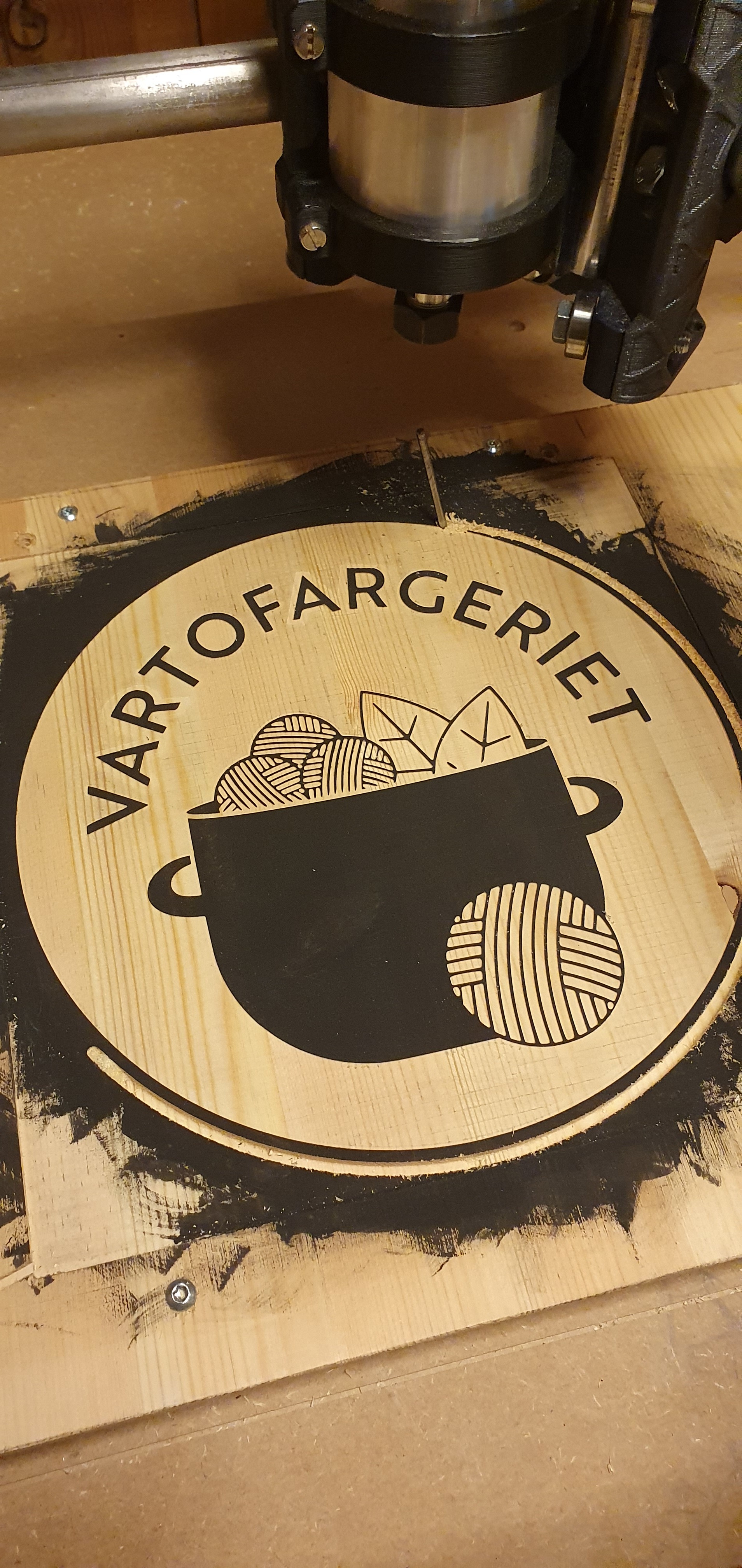
Yeah… I used the “gentle tightening approach” just now… and my “long bit” got dragged down and ruined the piece… I lost the border, but removed the ruined rim and now it’s okay, but it’s a shame that the border is gone…
Well, after this rollercoaster - I’ve learned that making several seperate gcode files is by far the easiest approach for my flaky brain! Especially because of the thigthening problem. This way I’ll manage the tool change on my own, I just have to keep a observant mind! (no radio documentaries in the background…) (I had to buy estlcam, couldn’t cope with all the waiting…)
One negative aspect with this approach is the small edges that are visible, because of homing and zeroing repeatedly is not 100% accurate. As mentioned in the other thread, the piece will need finishing up with sand paper and other methods still!
I use separate files and do not shut down the steppers. I move the router to a place to change bit by jogging to a open space then resetting Z 0. Then loading and running the next file. Never power down the steppers and you dont have to home except.for Z = 0
The Lowrider seems to have an advantage in this respect.
As it mounts the router base right to the 611 plate. It is easy to just release the clamp on the base and lift the router right out, to do the bit change.
I wonder if an easily releasable mount could be arranged for the MPCNC.
That’s actually what I ended up doing on the third tool change, after the bit fell out. I removed the router and changed the bit with the router standing on it’s head. The new tool mounts are very easy to open and tighten, since the nut is embedded.
I mount the workpiece to the table pretty much wherever. Home X and Y to the endstops, jog to where I want the 0/0 coordinate to be, make a note of that location in case something happens, zero X and Y, home Z using a touchplate to the top of the workpiece.
I use an IOT Relay to turn the spindle on and off with gcode. The relay is connected to the hotend pins on the board, so M104 S0 turns it off and M104 S200 to turn it on (200 is higher than the firmware dummy thermistor setting and thermal runaway is disabled in firmware).
Below is my Estlcam tool change script that I have evolved over time to something I have a lot of confidence in. I make use of frequent M00 commands to make me focus on the process because with that confidence and frequent use comes the tendency to not pay as much attention as I should. Having to methodically step through the process using the LCD forces me to focus on each step.
The general procedure is turn the spindle off and move it back to the home coordinate, disable the Z stepper (but keep X and Y active) so I can raise and lower it as needed by manually turning the lead screw, change the bit in the router, home Z with the new bit, turn the spindle back on and continue the job.
;Tool Change
;<n>, <d>, <f>,
M400 ;Wait for current moves to finish
G0 Z10 ;Raise Z to 10mm
M400 ;Wait for move to finish
M104 S0 ;Turn IoT Relay OFF
G0 X0 Y0 ;Return X and Y to home position
M84 Z ;Disable Z stepper
M00 <n>
M00 Home Z Touch Plate
G28 Z ;Home Z
G92 Z1 ;Adjust for touch plate
G0 Z10 ;Raise Z to 10mm
M00 Turn On Spindle
M104 S200 ;Turn IoT Relay ON
M00 Ready to go!
I’ve never had a problem with X or Y losing position while changing the bit. When I change the bit, I use the router itself as a helping hand. I lower it (manually by turning the lead screw) until the bit is barely above the workpiece, hold the router with one hand and press the lock button. That hand/arm’s focus is on not letting the router move at all. Then I use a long wrench to loosen the collet until the bit slips down and rests against the workpiece. Then raise the spindle until it clears the bit. Put the new bit in place and lower the spindle down on it until the collet touches the plastic depth ring on the bit while the bit rests on the workpiece. This way I don’t have to try to hold the bit by hand. Then tighten the collet the same way - one hand focused on holding the router stable, a long wrench to get leverage. Then raise the spindle with the lead screw before homing Z. All of that happens during the “M00 <n>” line in the script. The “<n>” is a variable that Estlecam replaces with the name of the bit I need to load.