Toolmaker build from germany

Hi.

Just got my mpCNC run, without big issues.
One of five steppercable was wired wrong (two wires inverted), that drove me almost crazy until I figured that out.

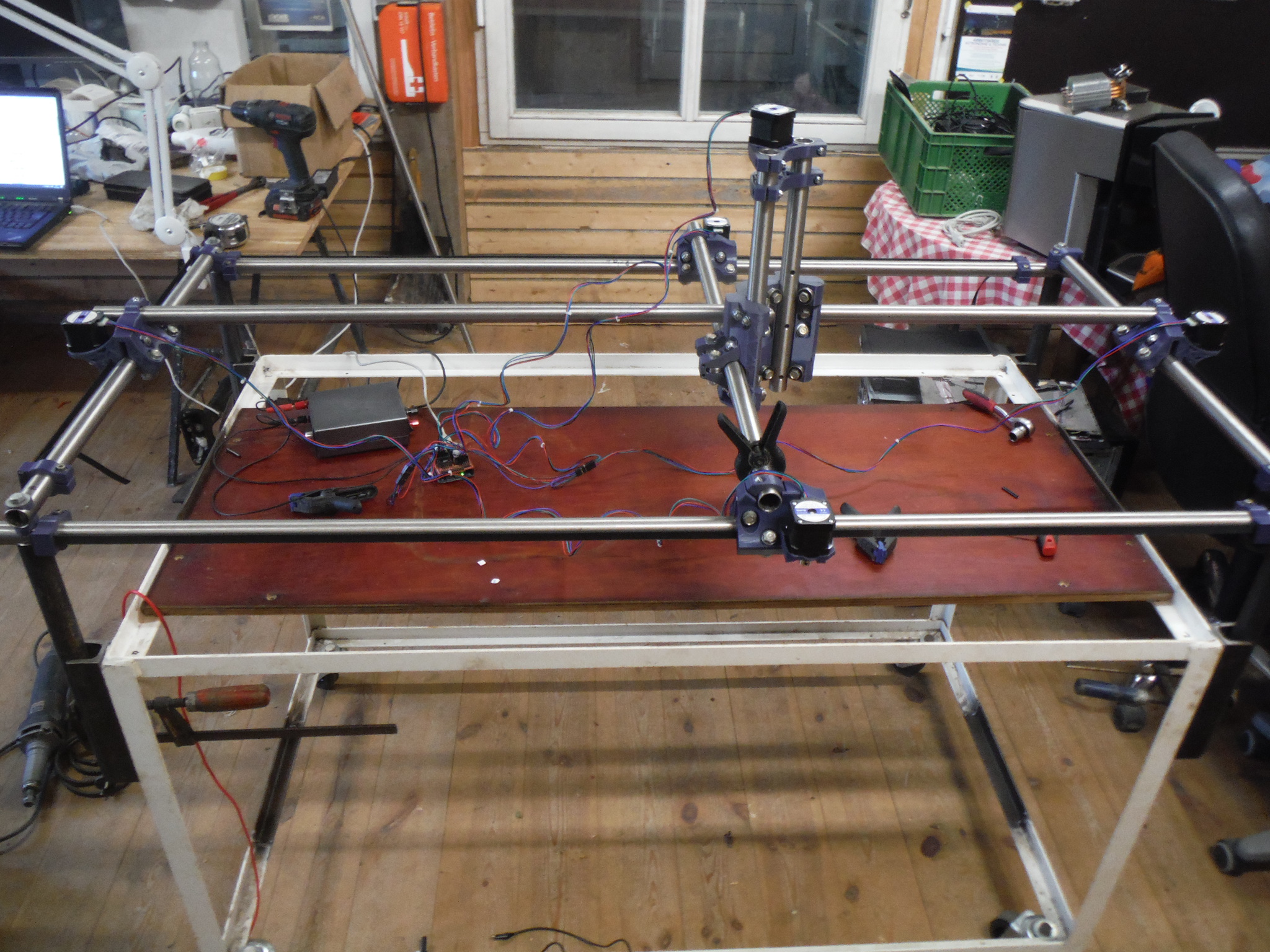
Main goal was to add as much as possible stability to maximize precision but also having a big working area.

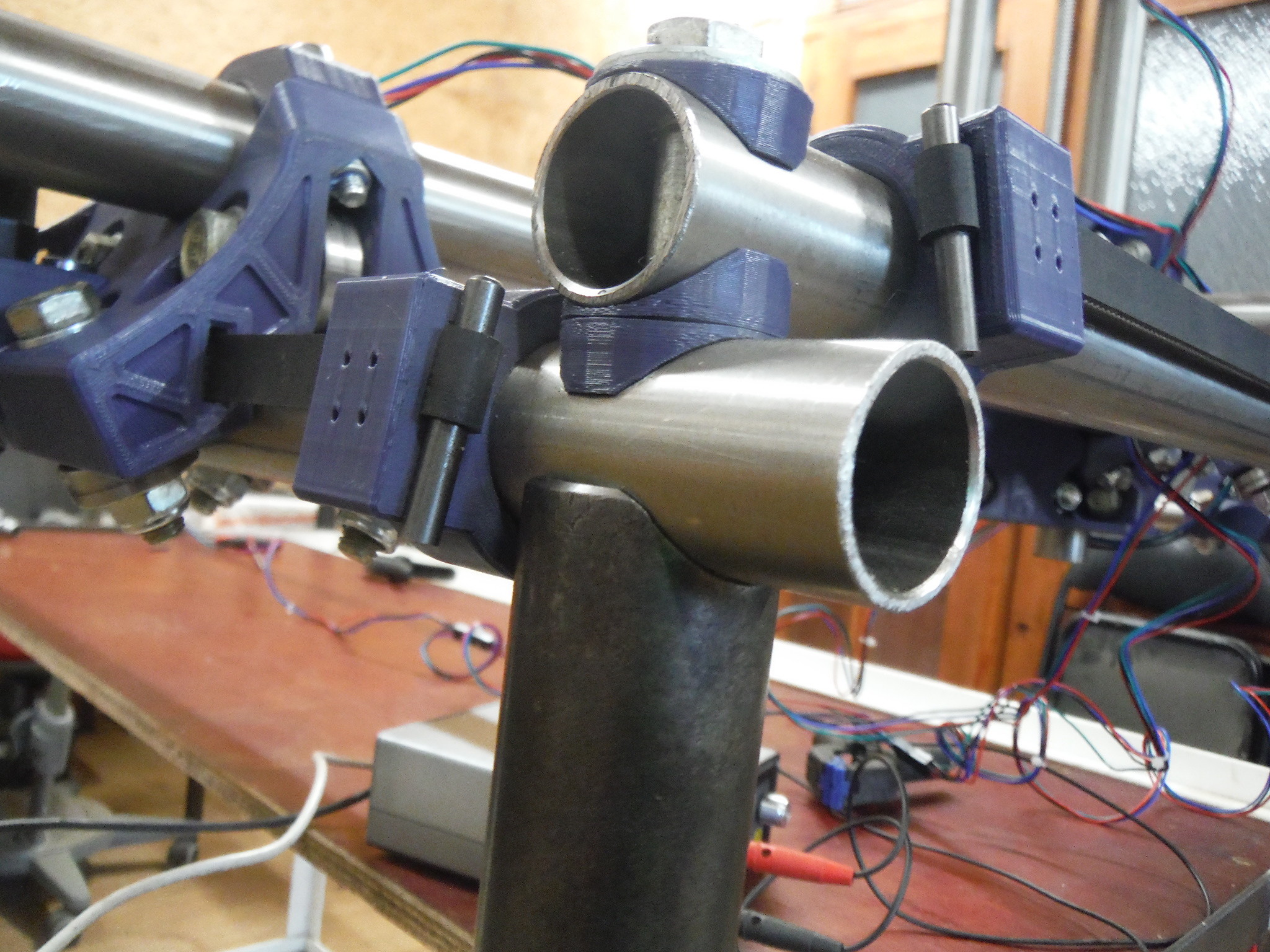
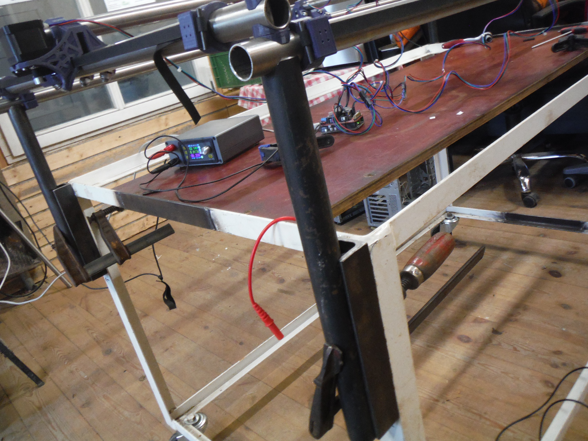
I used a available frame from an cart (got it years ago for free from a trash behind a hardware store). The corners and belt tensioners are very different from the standard, but I think this adds a lot rigidity. The vertical parts are 30mm full material. (just temporarely fixed with clamps)

The hole setup is adjustable in height, so I can work on thick material without having long Z rails.
Work area is 50x115cm. Frame is big enough to pass trough a a standard 125cm plate.
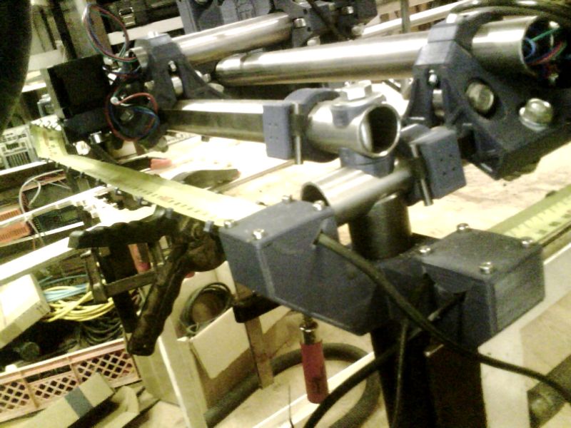
If I want higher precision/less vibration, the right bar including the truck is movable towards the left just by loosing 3 screws.

I used 25x2mm stainless steel for just 6,60€ per meter on ebay. Its not perfectly round and had a tiny bow (0,6mm per m), but I reduced it to 0,3mm and put the high part showing up, so its compensated from the weight on top.
Sorry, I cant behave different as a toolmaker :slight_smile:
If the X axis is vibrating to much, I might exchange it to full material.

In total I’m just at 160-170€ for all parts! (table, tool, black steel parts and computer/power supply excluded). Decent price for a CNC of this size!

I plan to put an old tower-PC below on the bottom (maybe headless with octoprint), use the power supply of it for the steppers and mount everything shielded inside to reduce the noise, esspecially during plasmacuts.

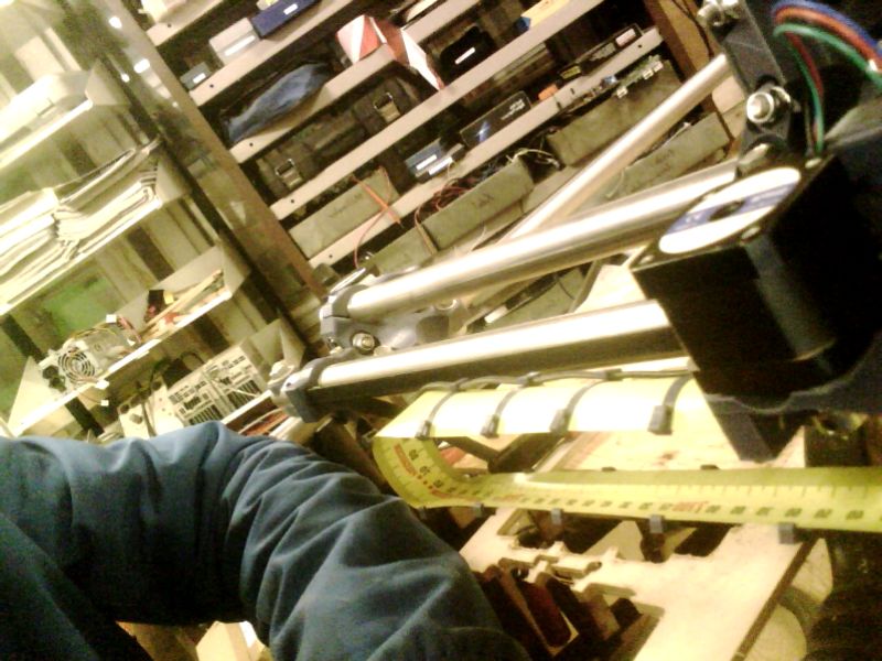
As cable guides I plan to try the tape measure cable chain.

I plan to use a router for wood/aluminium and a plasma torch. Rotary axis is also nice and I plan to use an existing dividing head for this.

2 Likes

1 Like

Cool! That’s a pretty big build for an MPCNC. It will be interesting to see how stiff it is when you get it running. Aluminum is going to be a challenge at that size based on other posts that I’ve read. You may need to add some center supports on the long ends but I think that could be easy with your design. You could even make them removable so you can work with larger workpieces. I look forward to seeing what you can do with it!

Interesting build. The core seems rotated, is it on purpose?

Yes, on purpose for 3 reasons:

I want to have the shorter Y-rails on top of the X-rails, so I can slide it to minus X to reduce the workarea and add stability if needed. That turns the head 90° ccw.

For me (right handed), the tool is much better to reach from the right without having a dusturbing rail, even more if I work in the lower left corner, what I will usually do.

The long rails are bit more stiff, because they sit tight in the radius of the vertical rods and hold down by M8 screws.

1 Like

Yes, thats exactly the plan: have a (removable) support under the X-rails. And I can move the right Y-rail just above it with little effort.
Using full material rods or thicker tube walls will also help a bit.

You will probably also get some rigidity by raising the work up. Having the Z reach down that far to mill can make it a bit loose.

Yepp, this is just for testing. Later the machine goes down a lot, so Z is sticking out just the minimum

1 Like

Nice build, I would appreciate if you could post more photos when its working.

1 Like

Here an picture of my cable guide. Used an broken 32mm wide tape measure and printed cable holders, every 5 cm.


3 Likes

Hi Folks,
here some Aluminium milling with Estlcam. Worked great!

5 Likes