Working on some test cuts and my parts seem to be undersized, I have checked the bits with calipers and i’m getting 3.18mm, I have tried different feeds and speeds and have not seen any great improvements. I am looking at the Gcode and while I can’t make sense of all of it, I am cutting square boxes with a notch so I would expect at one point Y would be a fixed value and X would be changing until it gets to a corner and then X would be fixed and Y would be changing. I am not really seeing this represented in the Code.
Some specs, Lowrider 2
Table Size 48" x 32"
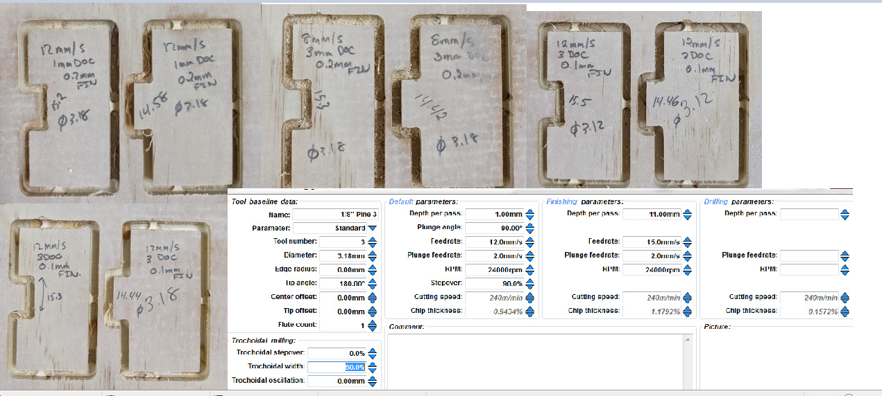
Two flute 1/8 endmill
3mmDOC
12mm/s
0.1mm and 0.2mm finishing passes using ESTL CAM
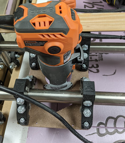
Ridgid router
I have checked my machine for square using a center mark and a 345 triangle, I am about .5mm out on the hypotenus on 500mm. 300mm and 400mm measure correctly using a tape measure.
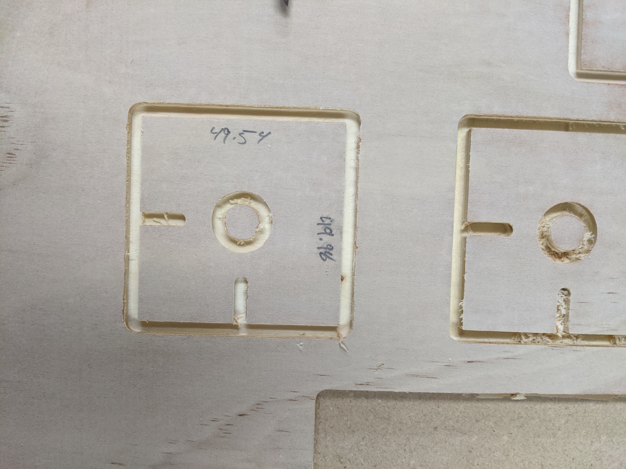
Dimensions shown on the wood are of the inside of the female tab and the outside of the male tab, they should both be 15mm.
Tool info below was for the final attempt at 1mm depth of cut. Gcode attached was for the first 3mm depth of cut (simply because it was a smaller file)
I realized now where the straight parts are in the g-code. I was expecting it as a point by point code but it’s more of a direction so a straight cut in x doesn’t need a y component with it. Duh. So now mainly chasing part tolerance when cutting.
So tonight I checked my z axis tubes and they were rubbing a bit on the table edge. I added some washers behind the wheels to bring the z tubes away from the table. I am running parallel tracks on the table as my machine was wandering a bit originally. I checked again for square and now I’m perfect on the diagonal of a 345 triangle to measuring tape accuracy. Checked the hole I drill by plunging the bit into the table and I’m measuring 3.18 on the calipers so there is no crazy runout on the router. I ran the cut files again and the slot is still oversized and the tab is undersized. I might try to get my hands on some foam to remove all load from the machine and see if that changes things. I did have a shitty 1/8 endmill with 1/4 shank that I tried and nothing improved. It was actually a bit worse but the bit was heavily burnt from earlier errors . Any suggestions would be appreciated.
It’s good to have some testing to find out what your machine is capable of and obviously you’re seeing some numbers you don’t like or are just hoping to improve. They don’t look all that terrible considering we’re mostly talking about a half millimeter or less. Depending on what you want to do with your cnc maybe this isn’t critical?
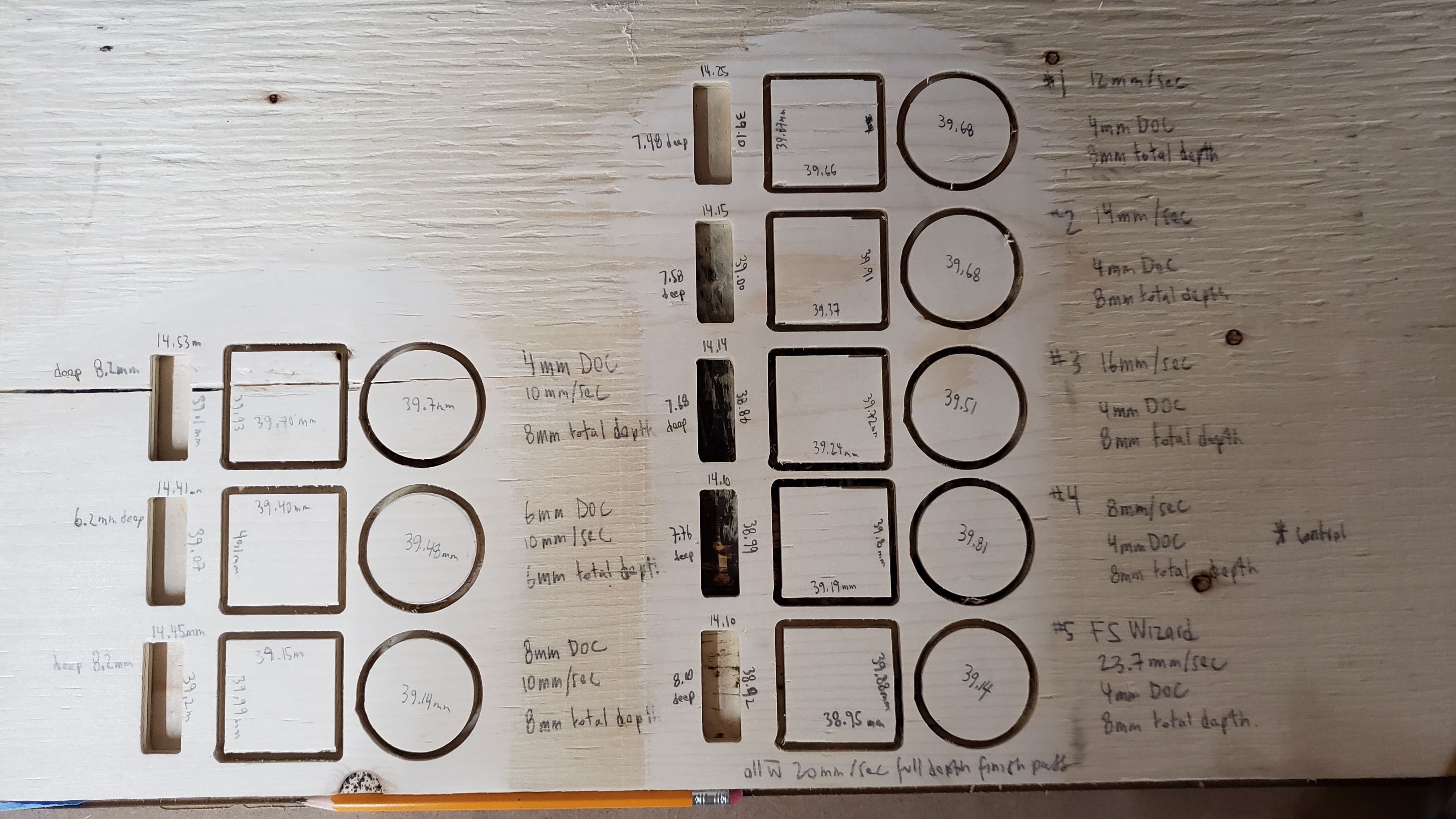
I ran similar tests for my own and produced numbers in the ball park but was pushing harder and deeper in my own tests. After many successes and failures I’d settled in on a feed of 8mm/s and 4mm DOC for most of my cutting. I’d heard of people going faster and deeper or slower and deeper and wanted to test for my own sake. Mine was all done with a 1/8" single flute upcut bit.
my circles were 40mm, the squares were 40mmx40mm, and the pockets were 14mmx40mm
With some reassurances from Ryan, my main takeaway was I can cut a bit faster and a bit deeper without breaking bits, this will save me a lot of time running the cnc so this was encouraging.
With my own machine, my table is 48"x30" and my x-axis is my long axis, and my wheels roll on the 30" side. In my photo the cutting was done with the up/down being my y-axis, and the left/right being my x. You can see pretty much across the board that on the long axis my variance was a lot higher on the cuts than it was on the short axis side. I’m pretty sure this is all belt related as even with what seems like high tension on the belts there’s that tiny slack uptake and the longer the belt the more stretch there is even if it’s a tiny amount it’s more the longer it gets.
Ryan did offer this too:
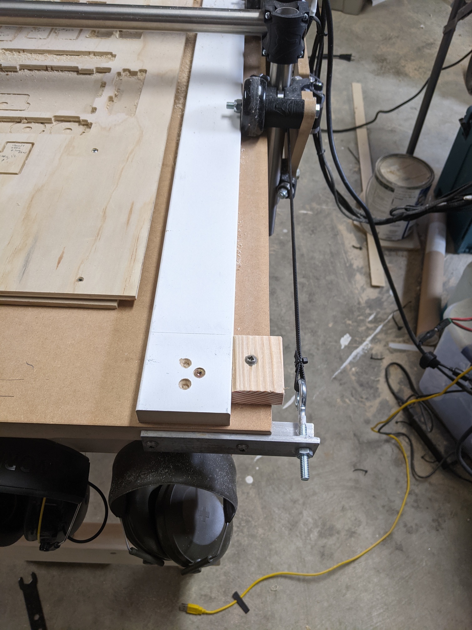
Some things in there to think on, let’s see your machine? Everything’s tight? belts, screws, running straight thanks to those gentle guide rails etc? How low is your router in the z travel when you’re cutting? how high/low is your router in the base when you’re cutting. I think Ryan often mentions the effect of the height of the gantry for rigidity and this sort of drag effect of deflection which may be part of what you’re seeing.
So you’re on a familiar path, and there’s been a lot of good info on here about this so good luck, test away, and show us what you end up finding.
I haven’t set us estlcam for myself so don’t be bashful about telling me so if I’m way off base, but is there any chance you’re cutting down the center of the part outline when the tool needs to be offset by its radius depending n whether it is an inside or outside cut?
Thanks Brent, that is good info, I have read all your posts about your issues. I understand that I am chasing zeros here these errors did not really effect my work until I started making tab and slot boxes, the tab and slots were very sloppy, didn’t cut deep enough etc which got me down this path.
Here is what I tried this evening:
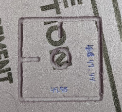
Cutting with and without a finishing pass in foam makes no difference. I made a new test code that is a 50 x 50 box with a 15mm hole and two 10mm lengths perpendicular to each other. Whether I run a finishing pass or not does not really make a difference. The Y (roller direction) is out more then the X, hard to measure foam with calipers but setting them to 50mm the box is noticeably undersized.
I was wondering if there was an issue with the g-code vs manual jog. I did a 300mm test using the display, and then 300mm sending a g-code command using repetier. They measure the exact same.
I then sent G-code through repetier to draw a 300mm x 300mm square and measured with the tape measure, I measured to the OUTSIDE of the slot so was getting 303mm in both directions. Corner to corner I was bang on as well.
This got my thinking, how could be I be .5mm out on a 50x50mm square but not out more on a 300 x 300. Of course one was measured with calipers and one with a tape measure so not exactly the best references but if it were a machine error you would think it would be magnified on the larger square.
I also removed the pulleys from the Y axis, measured the OD, cleaned and re-installed. Checked all the other pulleys. I even removed the router A/C cable from the cable bundle to eliminate potential interference.
My belts are hand tight with the zap strap, I don’t see any movement in them when its running.
I am running two flute upcut as it was a bit easier to find.
Z axis is as short as recommended
I appreciate the discussion, I am starting to run out of things to test.
Good thinking Tom, right now even the simple questions are useful. I am definitely running it as a part and the inside as a hole. This takes into consideration the tool diameter.
is your router plate like a 1/4" hardboard? The reason I ask is that’s a top heavy router mounted on a small footprint supported by what appears to be a thing board? That may wiggle a bit in back and forth moves.
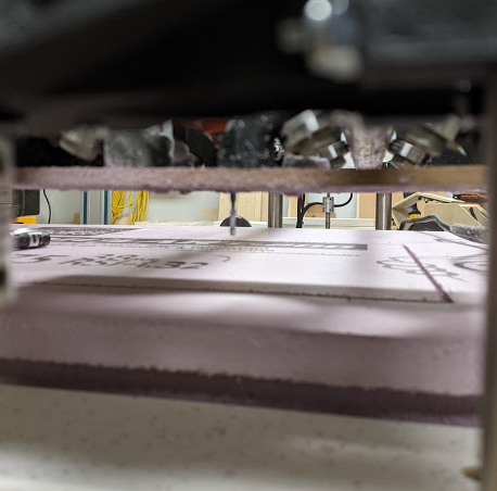
Also you are fairly high on your z tubes, have you tested right down on your spoil board on a thin board with these same tests? I realize the foam is quite thick so that may have just been for one of your tests but worth thinking on or checking. I know you said z axis is as short as recommended but I was getting at the height that the gantry is at when it’s cutting, not the length of the tubes. When the gantry is right down low on the table I believe that’s where our best rigidity is.
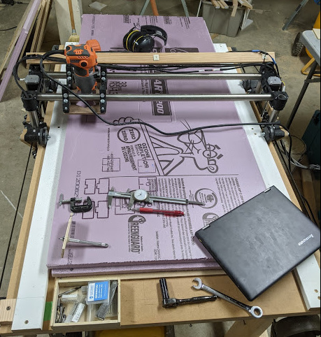
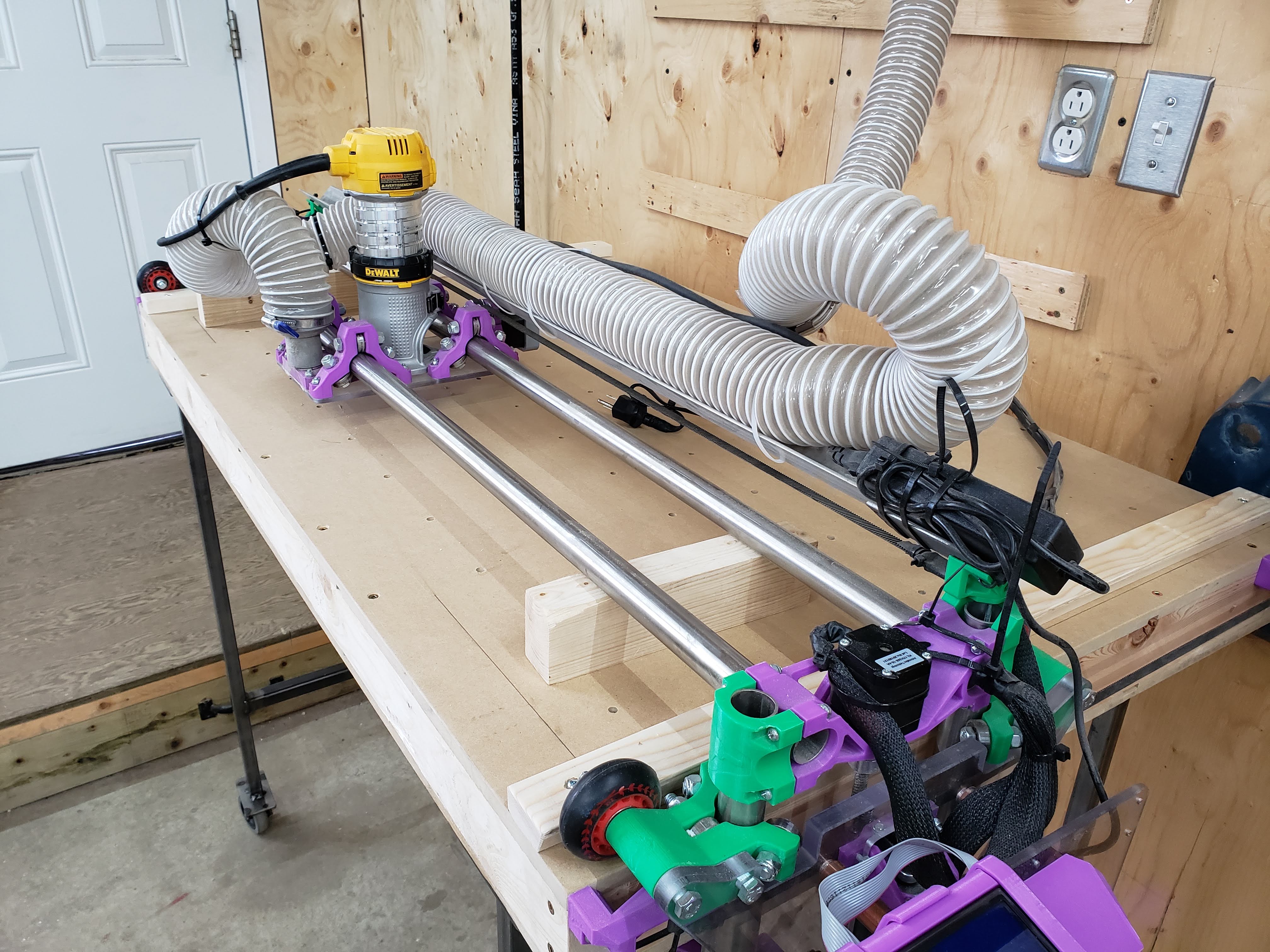
Here’s a shot of mine in the resting position but you can see how low my gantry is in comparison. With the 611 we can play around with that height a fair bit as we effectively have two z adjustments for the bit height which is handy.
Yeah, the z is only that high because the foam is 1.5" thick. The original wood test cuts were all done right on the spoil board and on the last cut I only had a few millimeters of clearance under the x y printer bracket and the wheel mounts. The router board is quite thin but the router is also a bit smaller than what you guys are using as it has a bit less horse power. It’s also all the way down in it’s holder so has a lower center of gravity then the one in your picture. I might try to cut a thicker router mount to see if that helps. I just used the one from the kit originally.
How tight did you make your Y belts? As tight as you could pull the zap straps with your fingers or did you also grab them with pliers to get a few extra clicks on the zap strap?
I think this evening I will try to run the largest square possible that I can measure with my calipers. If I still only have 0.5mm error then it is an error caused by the machine changing direction. Ie. Slop or flex somewhere. If the error increases with size then it’s a travel ratio error.
Brent, any chance you could send me the g-code of your best test cut. I want to see if my tolerances are reversed in direction to what you’re seeing.
There’s no magic sauce in my gcode, try the square out and see where you end up. I did use pliers to crank on my belts but have just printed these from @tailslidehttps://www.thingiverse.com/thing:3453813 and I’m sure they will be an improvement if not initially over time to be able to easily tension things.
For the gcode I use estlcam and all the basic settings from here. The feeds and speeds that seemed best were 10mm/s and 4mm doc. These will vary between machines but lost only a little by going to 6mm doc. The faster I ran the more pronounced my dimensions missed on my long axis but changed very little on the short right up to 24mm/s which was pretty jarring to my mind.
Thanks Brent, yeah I figured there was nothing special just wanted to eliminate one thing. I will cut your size box and see where it ends up. I suspect I will see similar dimensions. I also use estlcam without crazy modifications. I actually don’t have a 3d printer ( go figure) but I might just put some wooden blocks with some eye bolts on the end of the table to replace the tie straps. I don’t use the blocks to square up the y as I have added some to the top using a laser square to make sure they are bang on perpendicular to the Y axis rails. I datum off the wheels and not the z rails to eliminate issues with the z rails not being perfectly square
So I tightened the Y axis tie straps as much as I could and saw a noticable improvement in the Y axis. I installed some eye bolts in some angle aluminum to use as tensioners just to eliminate one area of play. This tightened everything up a bit and it’s cutting pretty good now. I might try adding some aluminum angle to the outside of the wheel plates because when I push on the gantry I can see the wheels flex our a bit. I will probably just run it as is for now as it’s much better then before.
That’s pretty good. If you really need an exact dimension you could try scaling one axis that tiny amount compensate. I haven’t tried this myself but I’m curious to try it now. If you can determine that the miss on the axis is consistent I bet you could get that tiny discrepancy back in your cam.
How would I scale it? Just manually or in an estlcam setting. I actually don’t think it’s linear I think it’s just a fixed amount of slop as when I did a 150mm square I was out by about the same amount.
More testing with different sizes or your intended work piece might help you determine the appropriate scaling. In estlcam you can definitely scale one axis at a time though. I’ll test out the idea and see how it turns out. I’ll bump the sizes up to see if there’s a rough % I can expect for each direction. For me what’s more important most of the time is getting duplication in the cutting from piece to piece rather than getting exact measurements however.