I just measured (approximately) what tensions I had got when I originally tried to follow the official assembly instructions without measuring tension, and they ranged from 1.9 lbs to 3.1 lbs. So at least some of them were outside the recommended range of 3-10 lbs, and they varied among each other by 50%.
More experienced builders can probably just tell what is a good tension, but newbies like me can’t.
Using the deflection formula, I think I now managed to adjust them all to within about 20% of 6 lbs (taking into account that I have a rectangular build, so the sides aren’t all the same).
Here is a picture of how I was measuring the deflection.
Too high. Two post above I listed the specs as 1-5lbf so you initial belt settings were absolutely perfectly fine. There should be zero functional difference between those numbers so if all the belts are different but in that range you are fine. What problem do you think the belts are causing you?
But the official assembly page ( https://www.v1engineering.com/belts/ ) says “the GT2 belts we use are 6mm wide, and should be installed at between 3-10 lbs of tension”.
Thanks for fixing the instructions. There is one other place on the page where it seems to still say “The GT2 belts … should be installed at between 3-10 lbs of tension (they can handle much more)”.
The problem I thought I was having was that diagonal movement seemed a bit jerky (remember that I had only about 2lbs on one or two of the belts). And since I had less tension than the official instructions page, I assumed that was related.
It seems smoother now at 6lbs. Do you think I should remove the zip ties and go back down to, say, 4lbs? I am really new to this.
I would honestly say just start using it and after some plotting and cutting we can revisit any issue that might pop up. There are many other things to learn along the way. Have some fun with it for a while.
I now wonder if the real limit here isn’t the radial load capacity of the motors. I have 17HS19-2004S1 motors from Amazon (your link is to 17HS19-2004S: I don’t know if these are the same or not) and I asked OMC-StepperOnline what the radial load capacity is. They told me it’s 21N. Given how the belt is arranged, the radial load on the motors is about two times the tension, right? That would suggest a maximum only around 2.3lbf of belt tension!
Am I missing something? I am now a bit afraid of damaging my motors. Though they seem to run just fine (I’ve only been drawing so far).
I know this is an old thread but I was reading it the other day and modified my tensioners with eye bolts. You might be able to equate the belt tension to the nut torque. If you have a really good dial indicator torque wrench you could use that. Most likely the torque required would be so low that you could cut a wooden arm that fits over the nut and hang a very light weight off it so it’s perpendicular. With a nylon washer under the nut to reduce friction it should be repeatable. Lots of online calculators to correlate but torque to clamping force. In this case clamping force = belt tension.
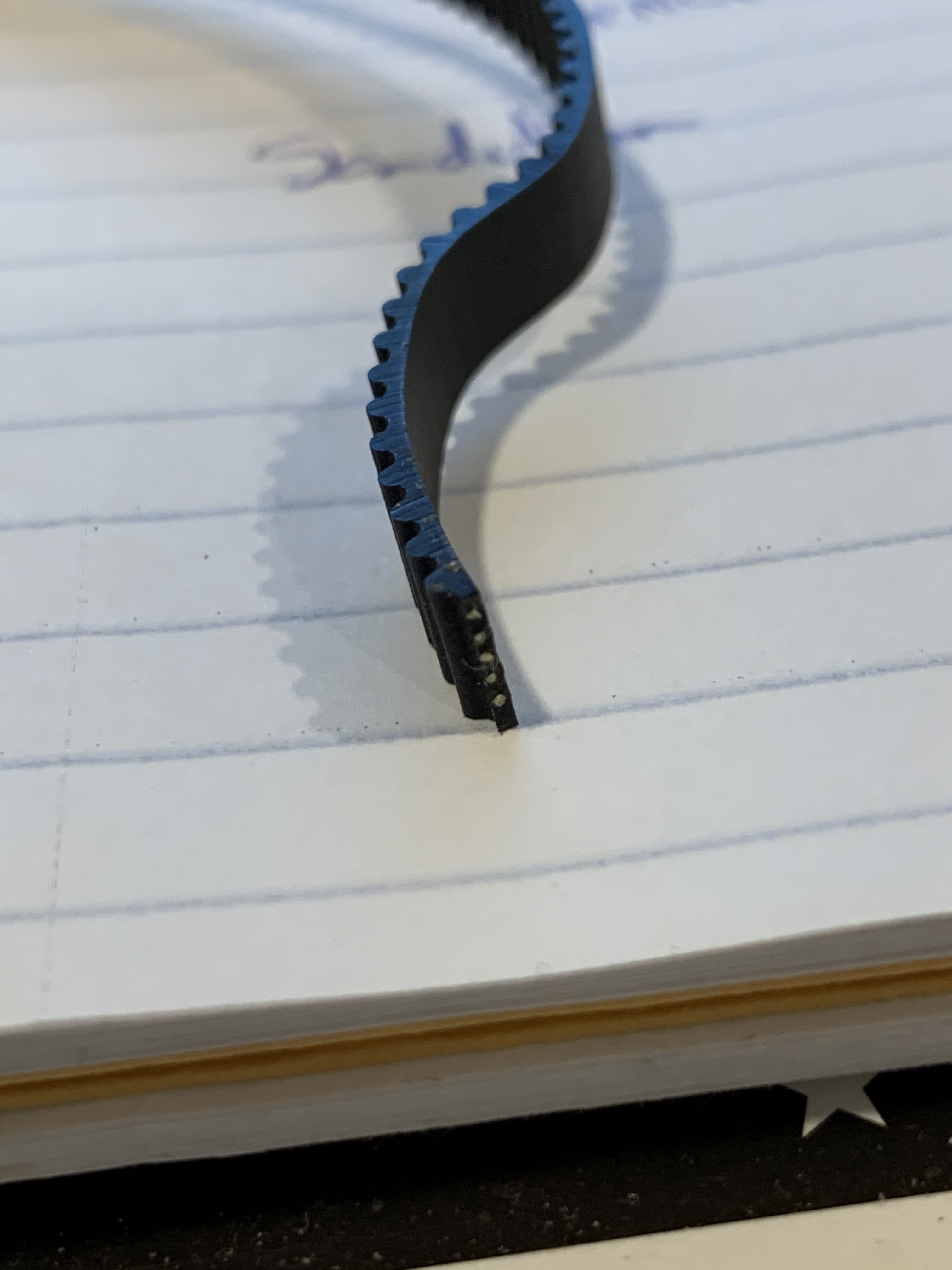
Speaking of belts… My MPCNC feels too “bouncy”. Like, when the stepper motors are locked in place, I can still get some “wiggle” if I try to move the tool mount by hand. Doesn’t take too much force. I also find that when Lightburn is throwing the laser around for line work, it will sometimes accelerate hard enough to cause a skipped tooth. Before I try to escalate the belt tension, does this belt look like it’s properly reinforced?