Once you build in VS Code (assuming you build normally) the “firmware.bin” file gets placed at this folder location:
marlin/.pio/build/BIGTREE_SKR_PRO
(the last part, above, varies by device/board).
I’ve never used those buttons that seem to be intended to put the file into some specific place. Im sure they work.
Tip: you can use the file browser on the left side of VS Code to browse to the rendered .bin file, and right click on it, and choose “Reveal in finder” (that’s the Mac option, and I would assume there is a Windows version of that).
Note: on a Mac, by default, the .pio and etc are normally hidden. If you are trying to browse to them without using VS Code, you would probably have to do something show hidden files and folders.
Thanks, Doug! I’ve gotten my firmware.bin file and placed it in the root of my microSD card. Do I need to unplug the TFT display when running the update?
Okay, I successfully compiled the code and updated the firmware. I confirmed by changing the name of the machine, which I can now see on the display, so I know that it’s my compiled firmware.
Per @jeffeb3 , I uncommented //#define SERIAL_PORT_3 1 in configuration.h and changed it to #define SERIAL_PORT_3 6
The pendant is still not controlling the MPCNC - no response to any joystick or button input. I took the pendant and connected it to my laptop and used arduino’s serial monitor to verify that yes, the Gcode commands are being sent to serial.
I also tried swapping the rx and tx pins coming from the pendant, but that also did not work.
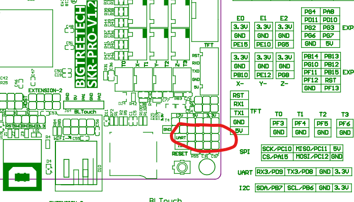
I know there is both 5v and 3.3v on the SKR Pro, but im a bit concerned that the tx and rx on the SKR Pro are 3.3v pins being fed 5v by the Arduino. If that is not a concern, could you unplug your display and use those rx and tx pins to test your pendant. You know those two are active. My internet is down, so i cannot research easily. What rx and tx pins are you attempting to use?
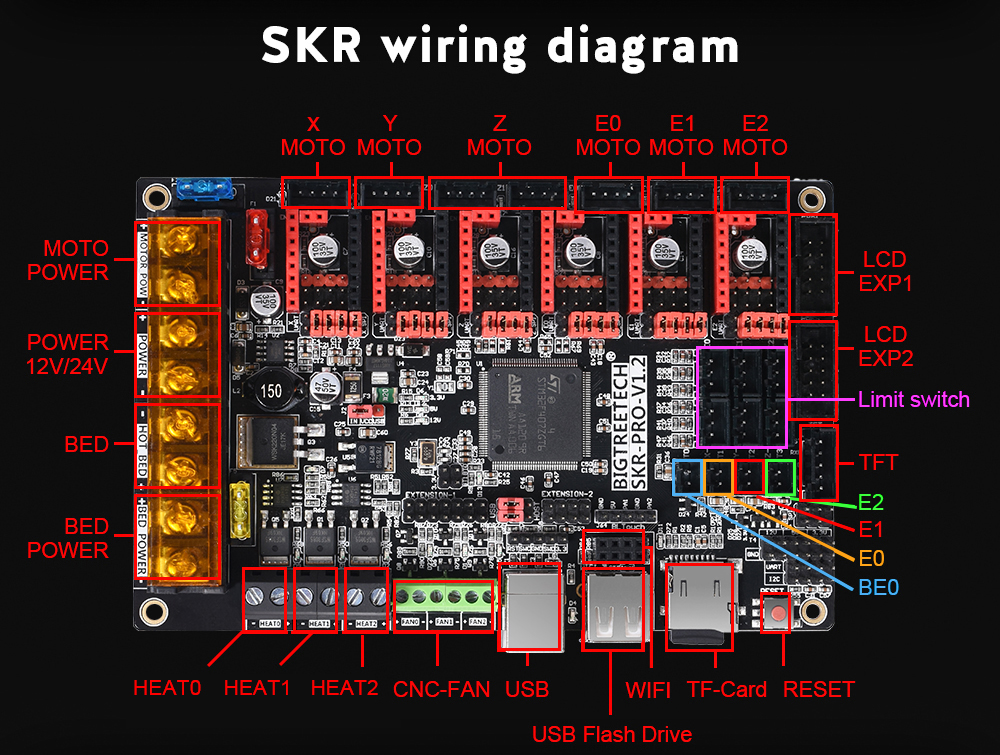
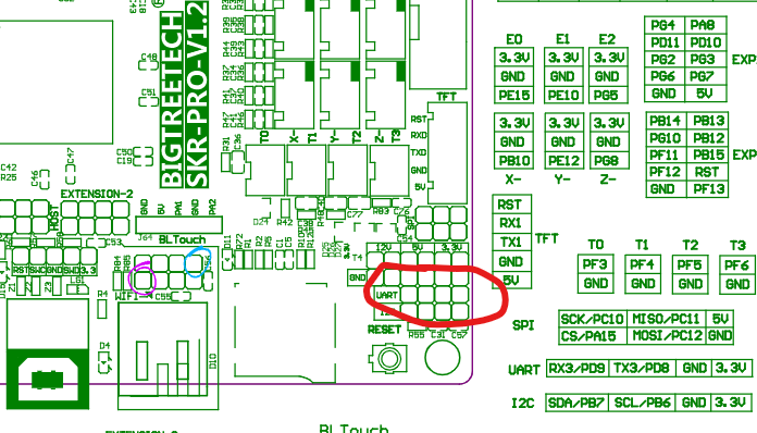
I’ve used that uart to flash the bootloader. I don’t know what number that is in the firmware. The 6 is on the wifi 2x4 pins next to the USB-A connector:
The wifi dongle is an esp01 esp8266. Judging by that, Tx is circled blue and Rx is circled purple:
Thanks, Jeff! I’m concerned now about Robert’s point about the voltage. If the pro micro I’m using is 5v, do I need to replace it with a 3.3v before trying again (and hope I haven’t already burned out something trying the other UART)? I know there are logic level converters - maybe I need one of them?
I might try plugging into the TFT pins, just to see if I can get it working. Last I heard, the touch screen doesn’t work anyway.
Okay, it works when connected to the TFT pins - yay! I guess I’ll leave it hooked up that way for now, since TFT doesn’t work anyway, unless someone has a better idea.
With respect to voltage, my only concern is the TX signal from the Arduino to the RX on the SKR Pro. When I’ve done this kind of thing in the past (Arduino’s only), I’ve used a two-resistor-divider circuit to bring the voltage down to 3.3V. I’m just a hobbyist with electronics, so Jeff is a better resource to know if this is necessary/advisable.
Unless your Arduino is reading from the SKR Pro (like using M114 to get the position or are reading the acknowledgements), the wire from the TX on the SKR Pro to the RX on the Arduino is not necessary.
Grr. I was all happy to have the pendant working, and just wanted to make some adjustments to the codes sent. Made the changes but can’t get the sketch to upload. Don’t expect you guys to help me with that particular problem, just venting.
The resistor divider is a good trick, since there isn’t much current flowing.
I’ve also had good luck just putting a single resistor in serial on that line from 5V tx to 3.3V Rx. The idea is that there is a voltage differential, and some current flows to the poor, 3.3V microcontroller, but it gets reduced to a fraction of a mA with a 10kOhm resistor. Enough to just protect it.