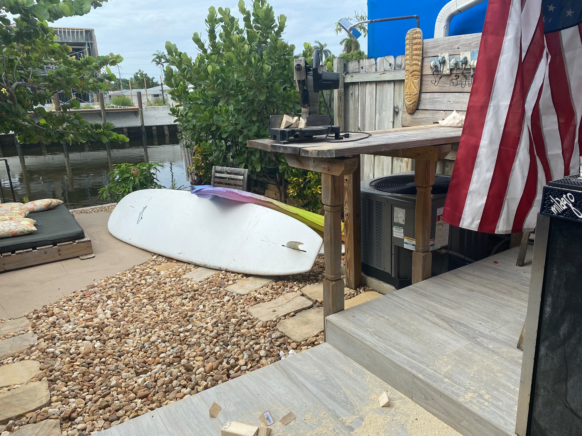
So I built the frame for this and have it partially setup. Assembling the Lowrider the x zip tie clamp snapped off on me when I stuck the zip tie in there, must have had an issue on that layer when printing. I ordered more of the red PETG that I printed this with to print that part. I was able to rig it with a zip tie directly to the exposed tube, and worked fine to set up and test. Everything went well except for an issue I had on my z axis which made a wobbly mess out of the coupler. Re ordered a six pack of those in case this happens again. So my z is not working at the moment. But I got it all setup before it did that. All the things I ordered were supposed to be here yesterday now it says Wednesday / Thursday… Top off the day or two of Reprinting / printing the clamp/ vac duct I am designing for my router. Current progress sorry about mess finishing the build on my a/c closet and washer dryer counter top…
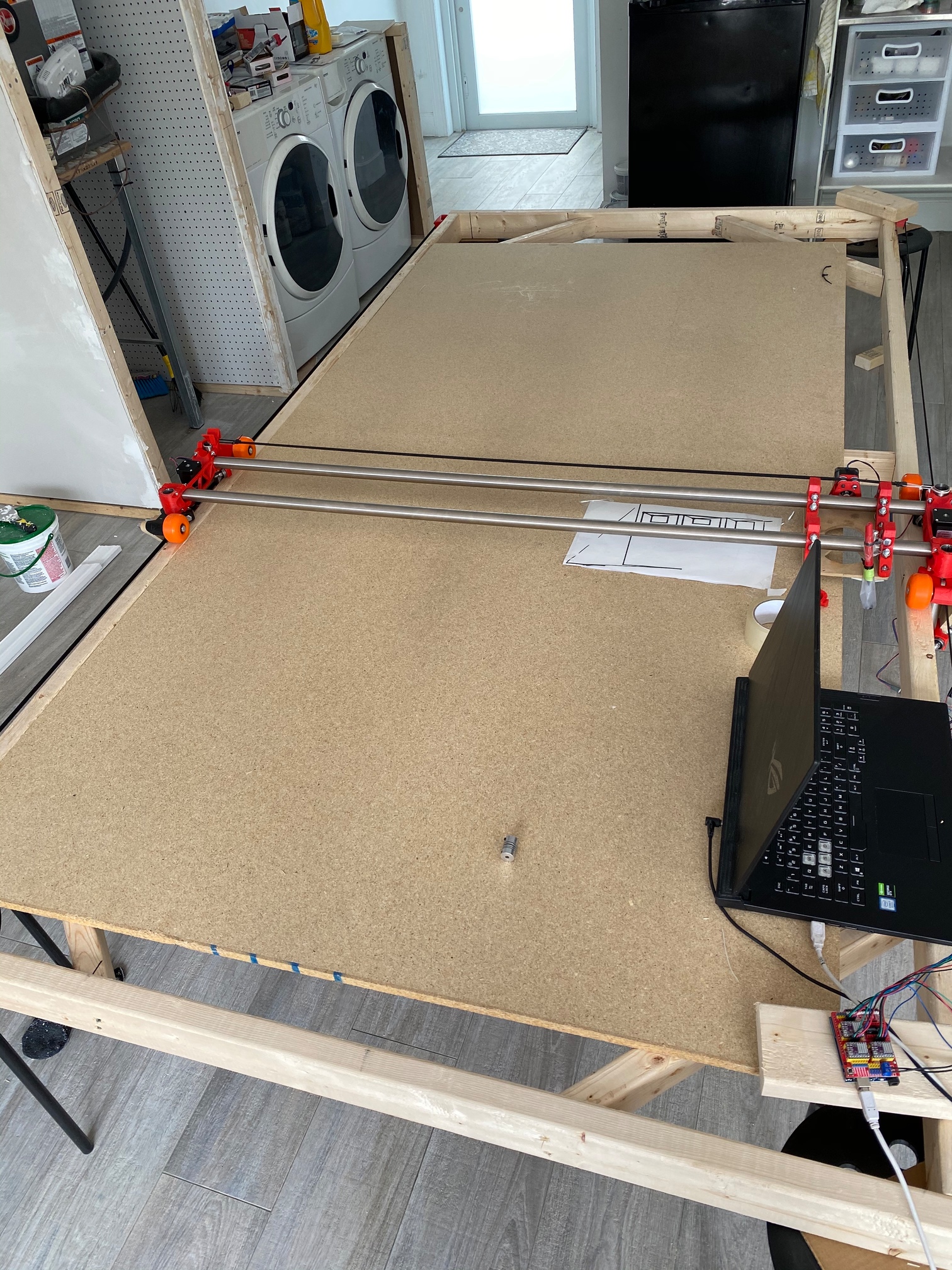
It’s working great with pen attached just no z so you see the travel lines .
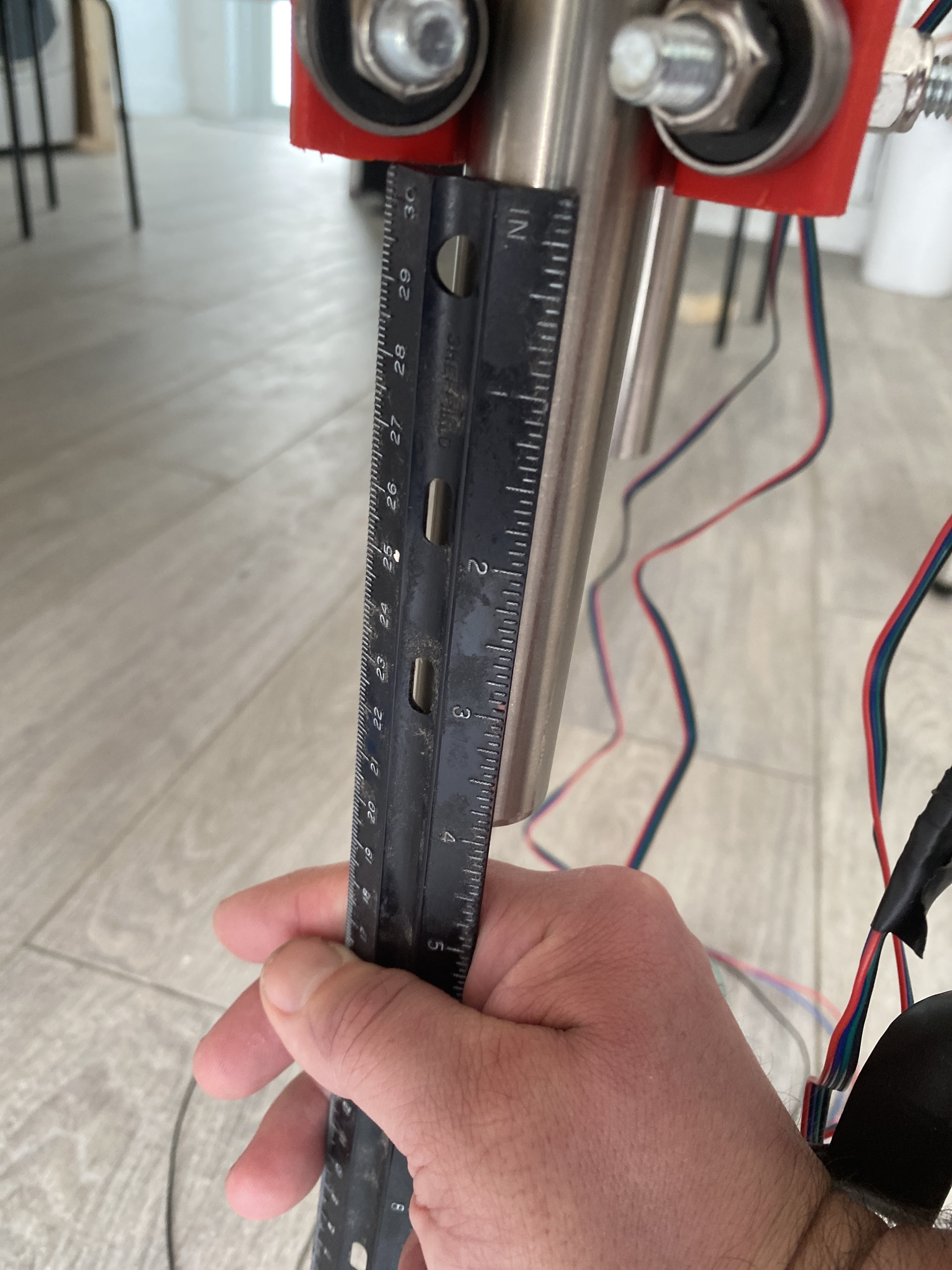
Now I don’t understand why the z axis keeps going beyond the max limits I set in GRBL . It was zeroed out at the bottom , I went up and it popped off the rails even tho a max was set in GRBL causing the coupler to bend and get out of whack, I know I should have done it incrementally but I noobed on it and paid the price of having to wait to finish the build and buy $6 couplers. Current settings
$0=10 (step pulse, usec)
$1=25 (step idle delay, msec)
$2=0 (step port invert mask:00000000)
$3=0 (dir port invert mask:00000000)
$4=0 (step enable invert, bool)
$5=0 (limit pins invert, bool)
$6=0 (probe pin invert, bool)
$10=3 (status report mask:00000011)
$11=0.010 (junction deviation, mm)
$12=0.002 (arc tolerance, mm)
$13=0 (report inches, bool)
$20=0 (soft limits, bool)
$21=0 (hard limits, bool)
$22=0 (homing cycle, bool)
$23=0 (homing dir invert mask:00000000)
$24=25.000 (homing feed, mm/min)
$25=500.000 (homing seek, mm/min)
$26=250 (homing debounce, msec)
$27=1.000 (homing pull-off, mm)
$100=200.000 (x, step/mm)
$101=200.000 (y, step/mm)
$102=3200.000 (z, step/mm)
$110=1800.000 (x max rate, mm/min) * 16 teeth pulley : GT2 belt
$111=1800.000 (y max rate, mm/min) * 16 teeth pulley : GT2 belt
$112=180.000 (z max rate, mm/min) * T8 leadscrew with 2mm pitch
$120=100.000 (x accel, mm/sec^2)
$121=100.000 (y accel, mm/sec^2)
$122=50.000 (z accel, mm/sec^2)
$130=2629.000 (x max travel, mm)
$131=1244.000 (y max travel, mm)
$132=270.000 (z max travel, mm) * z rail is 12 inches 270mm is 10.63inches
It kept going / running even beyond 270Mm
I was doing it in cnc.js just hitting the +z … yeah kinda ridiculous at like 50mm increments. It was zeroed at the bottom.
Also I haven’t built the legs for this thing yet because I’m not sure weather to keep it stationary or put on casters, or figure out a way to be able to make it go diagonal for storage when not in use… I have a makeshift bar/ outdoor kitchen which I was originally going to beef up With more support at the edge and screw down the floating edges to level. That’s where I originally had in mind for this. Then I built the full size 4x8 version to have the capability to build all the cabinets / entertainment system for my house, then deconstruct / shorten pipe to fit on the bar outside , or turn into mpcnc. Pain to move this frame with one person but do able , you think that bar with the added post on edge would be enough to support / keep the frame which is much bigger then it’s current size ?