I would like to share my ideas which I had after I realized some chatter in direction of the Y axis while cutting my last aluminum project.
After looking closer on the bearings and the rollers, I found out that some of the bearings where a little loose. Most of them came back in touch with the tubes by tightening the M8 bolts, but some did not…
Of course, PLA prints would have been more rigid than my prints in PETG, but I like printing the BASF Ultrafuse much more somehow
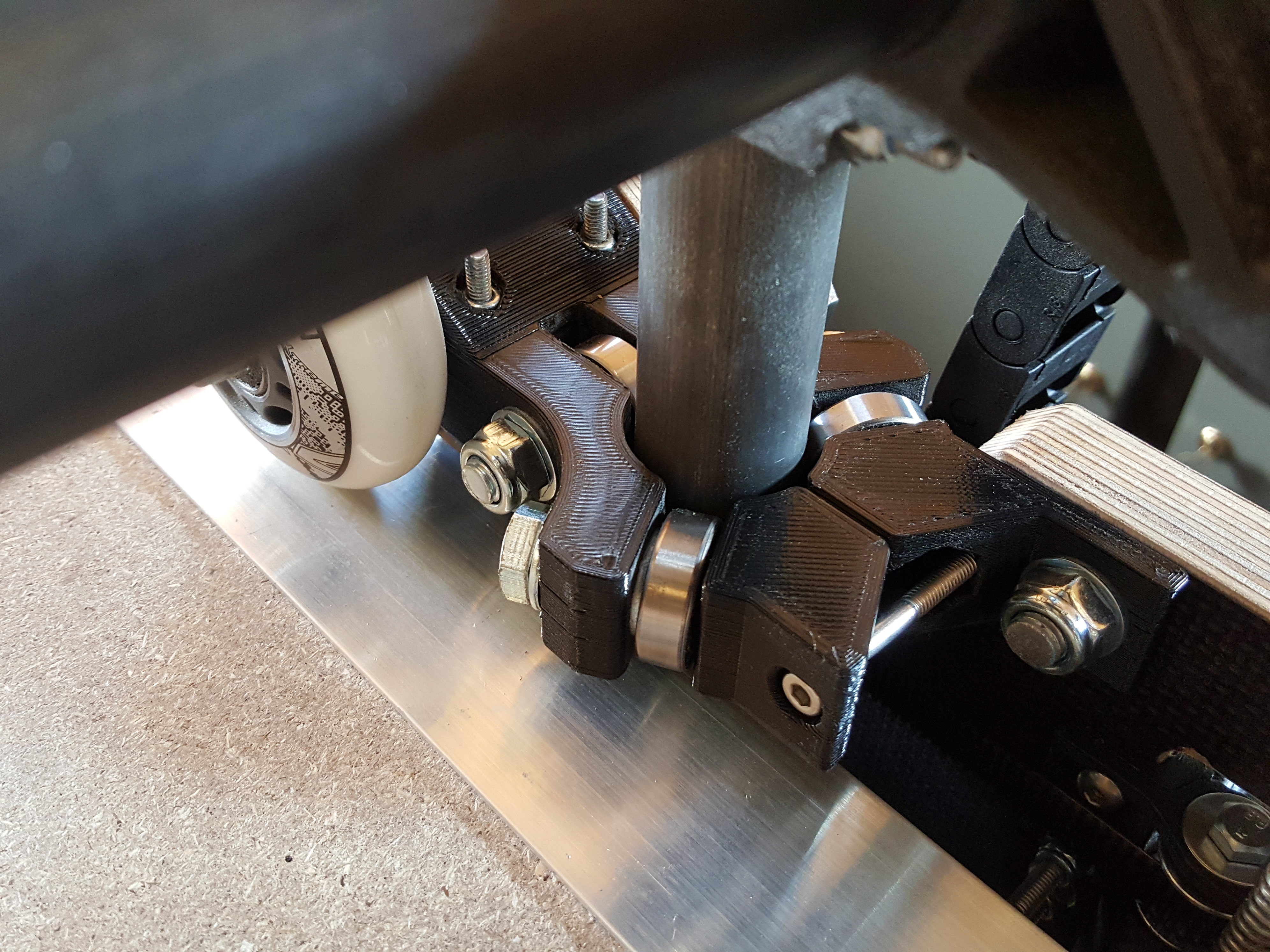
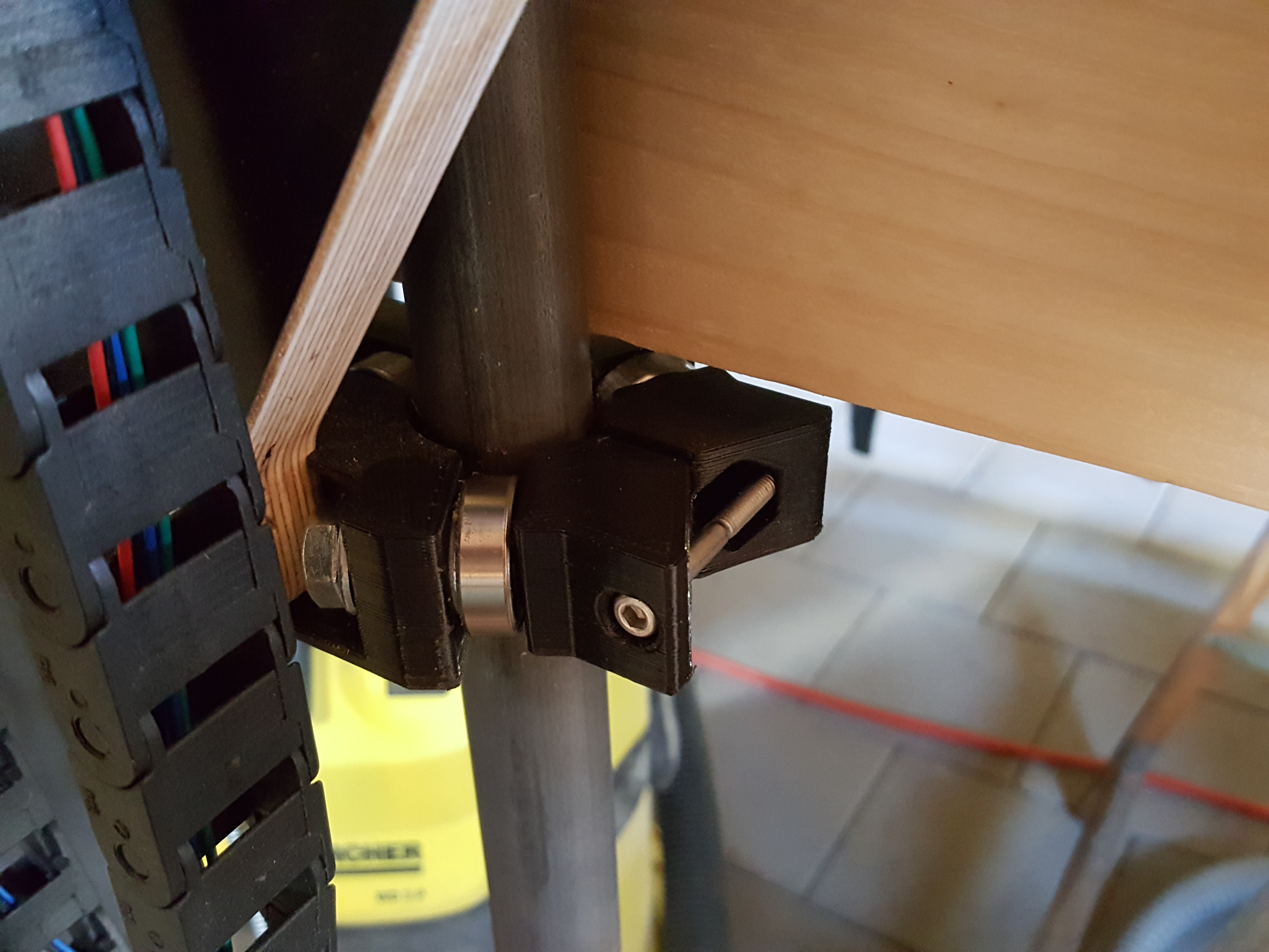
So I decided to design something to thighten up the ‘arms’ of the rollers directly by a M4 bolt and to support the outer arm of the upper YZ-roller with an additional M8 bolt attachement to the Y plate.
After installation on one tube, it feels much more rigid than before! I will see what happens when I upgraded all rollers and when I mill some aluminum again…
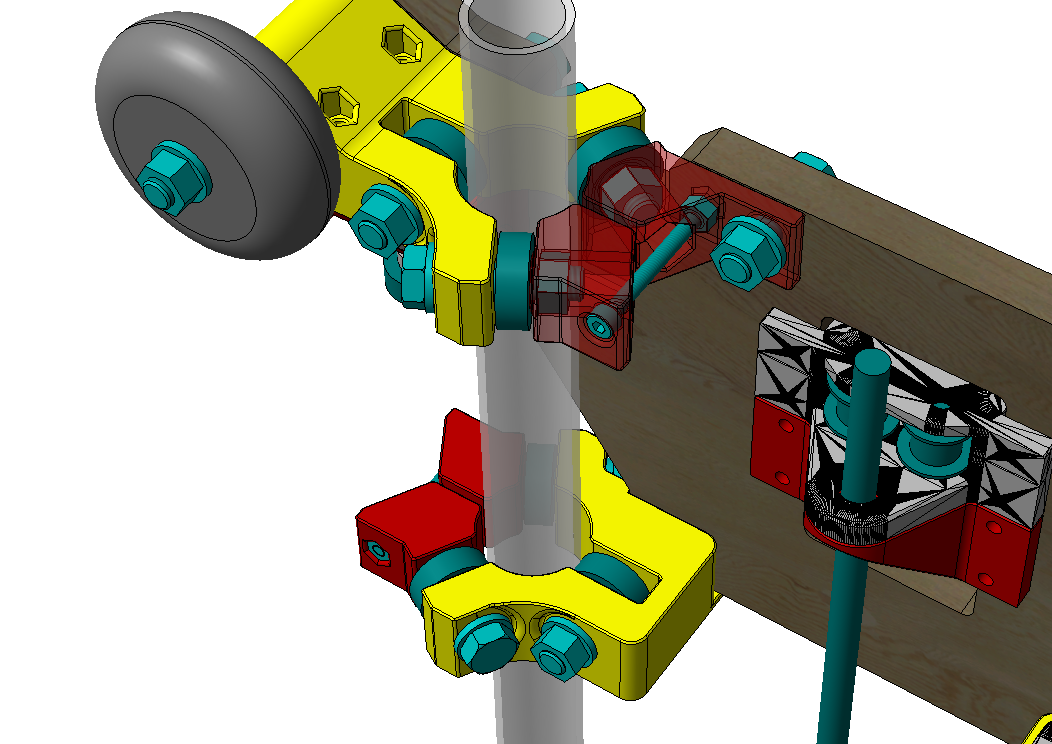
A Picture from CAD.
Yellow parts are redesigned because I prefer to use washers between the bolts/bearings and the printed parts. Red parts are additional brackets and supports.
Thank you! Setting the correct tension is pretty easy.
On rollers with one loose bearing, just thighten the M4 bolt until this bearing shows enough friction on the tube again.
You can feel that when you try to turn the bearing with two fingers
In the past there were several ideas and designs for more rigid and printable XZ main parts.
In my opinion every printed version does not fullfill my expectations on a more ridgid Lowrider…
But in fact I really like the original design from Ryan!
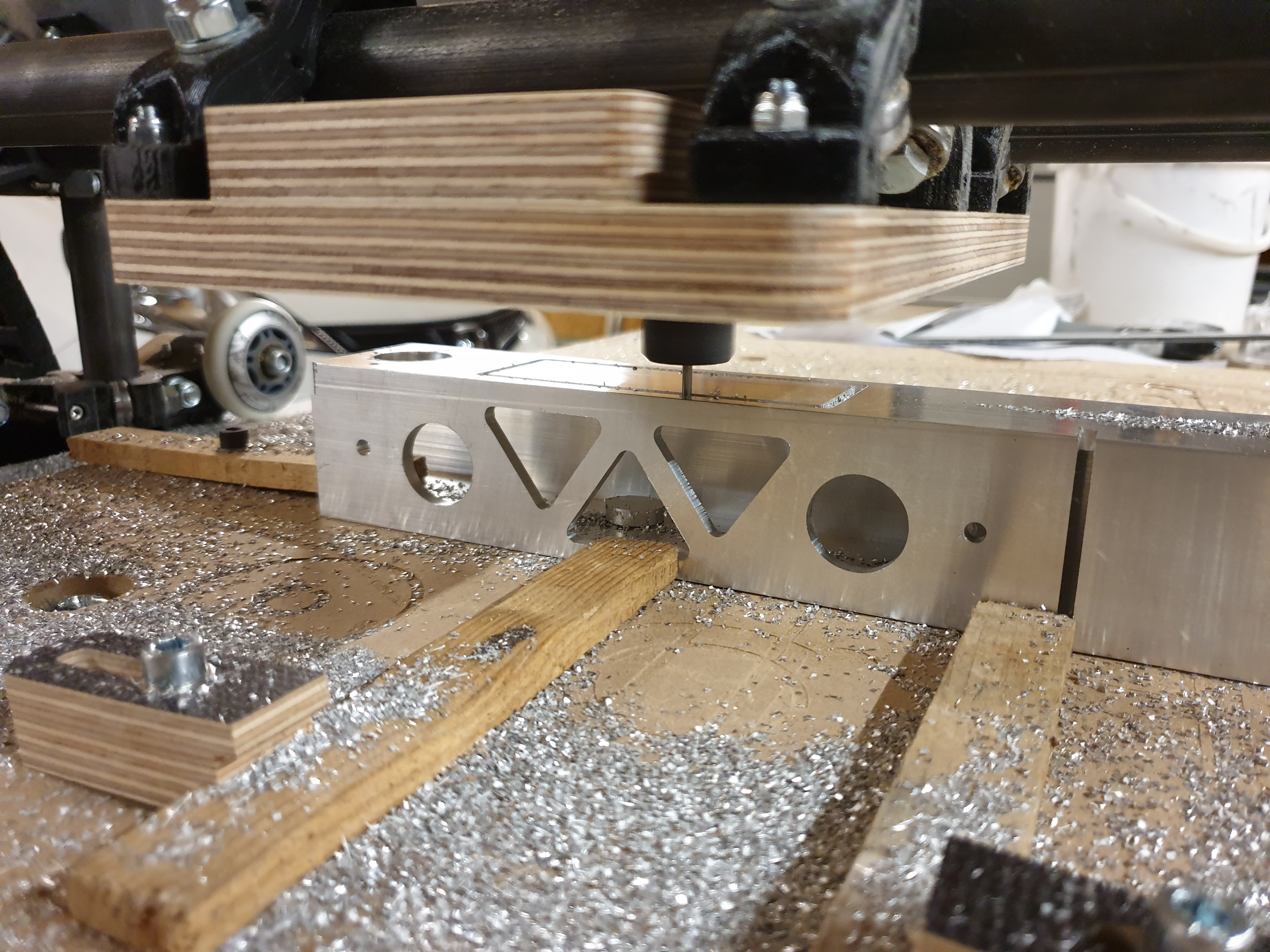
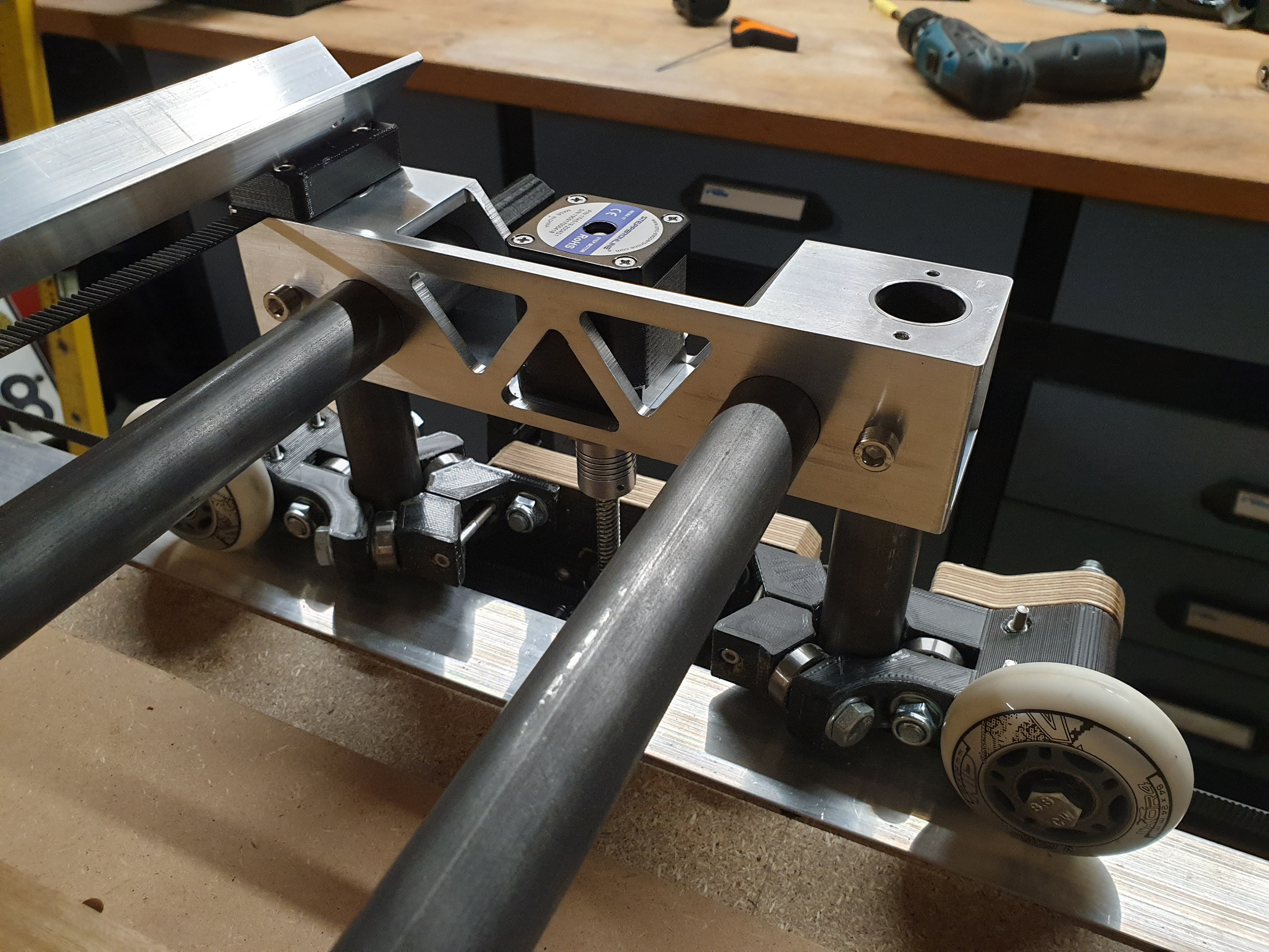
So I looked for a different material and found a cheap way with some 50x50x5mm aluminum extrusion profile.
It is a 4 side milling job - 3 sides are already finished. Looks good so far.
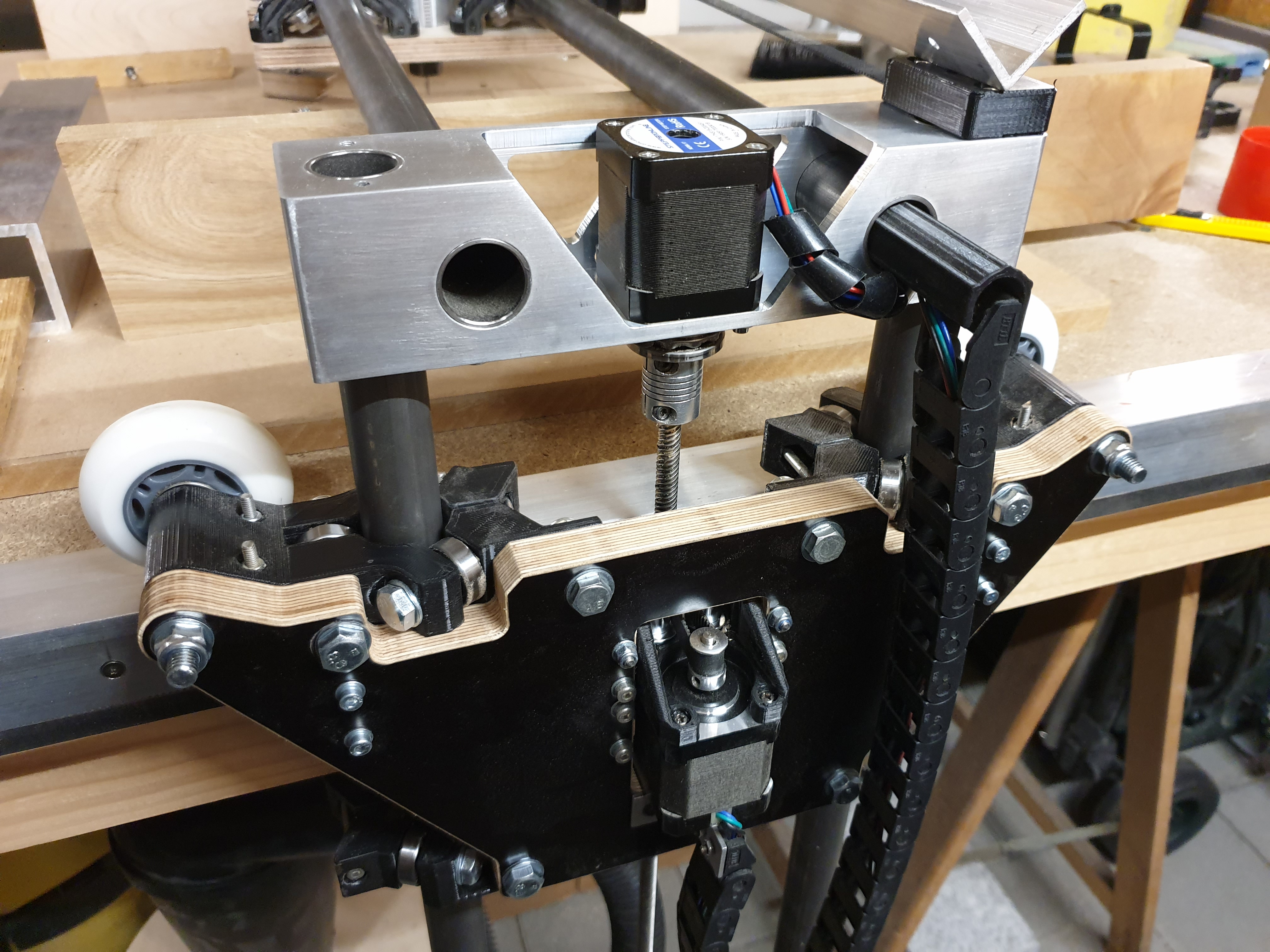
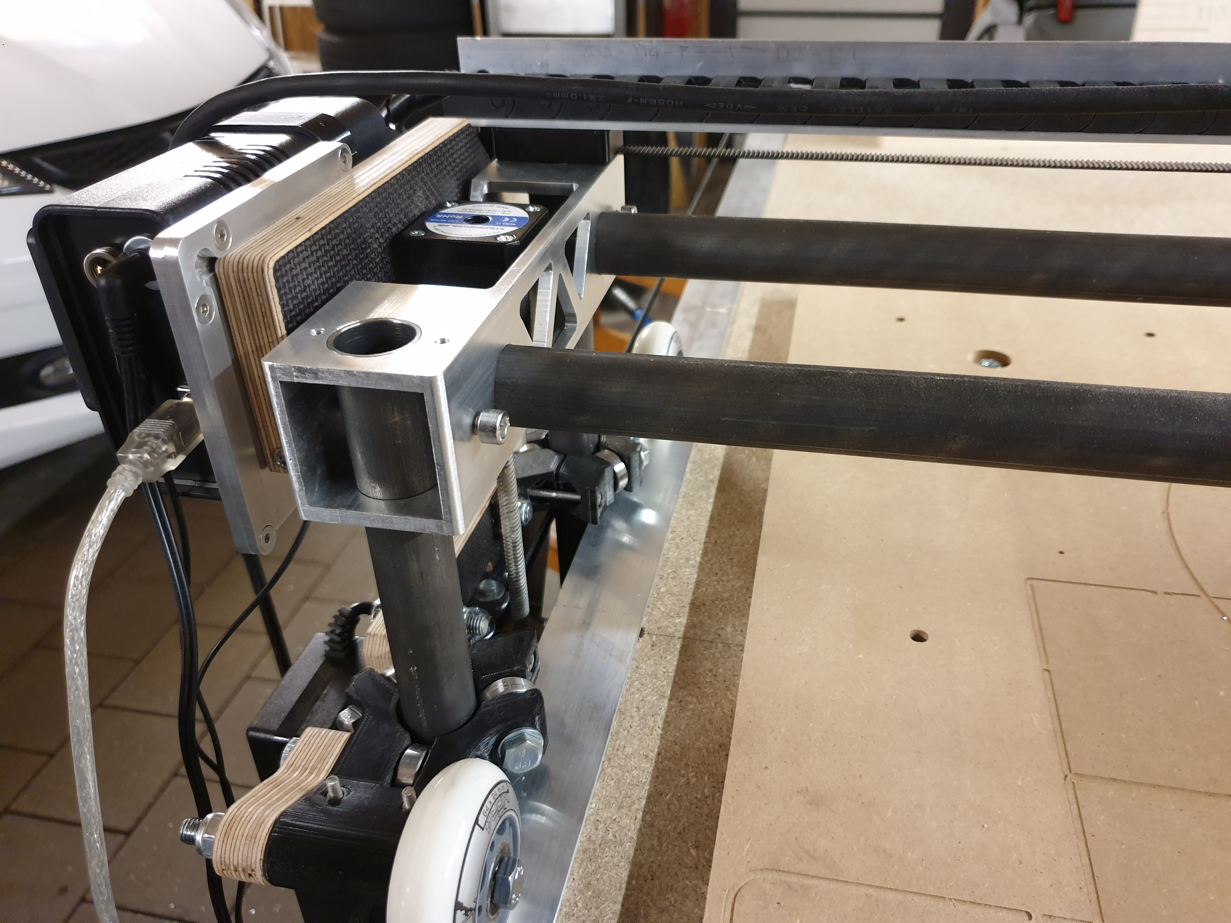
I will post an update when the first side is assembled
Of course! I will share the CAD file on thingiverse.
And in regards of the 4 side milling - I use the automatet zero point function of Estlcam. Instead of the touch plate I use the workpiece itself… In this way, there is no need to fix the workpiece in the exact same position after it is rotated for the next side.
The only thing to care about is that the aluminum profile has to be cut square on the left reference plane