@Rich Ooooh, nicely done sir. Could you by chance share the CAD files?
1 Like
Thank you!
I just uploaded it to thingiverse 
7 Likes
Thanks!
Rich,
When you get a chance, can you describe your set up as it pertains to probing/locating? Considering the success you’ve had milling multiple sides I’m quite interested in learning what hardware/process you’ve implemented.
2 Likes
I attempted to view the DXF file in Fusion 360, but it is not scaling properly to 50mm on the short axis.
Would you be able to provide the center to center dimensions of each of the pipe holes, along with any off-sets from center necessary for these, as well as the stepper offset?
50mm X 50mm square tube is not available to me, and I need to modify for 2 inch by 2 inch with a 1/4" wall. It’s close, but it’s not quite exact.
I will have a look on it tomorrow. I think it’s easy for my CAD to adjust it to 2"×2"
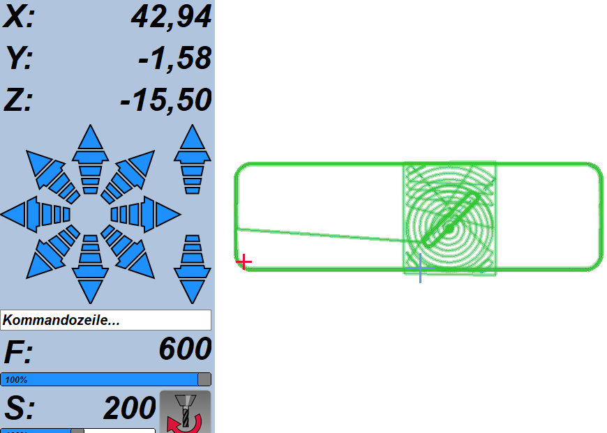
Can those that have done this using the LR2 to do the milling what bit, feeds, and speeds you used so I have a starting point.
Did you tap the aluminum for the screws to hold in the pipes?
I did that job with a 3.175mm single flute aluminum bit. 400-600 mm/min at 1mm DOC.
I had the Makita on stage 3, so about 20k rpm.
2 finishing passes on the pipe holes will bring you more accurate diameters than only one pass!
And yes, I tapped M6 threads into the 5mm holes
3 Likes
Hi Rich, thanks for sharing your model on Thingiverse.
I’m planning to mill those aluminum parts and have a question.
In US I can only find 2x2 with wall thickness of 1/8" (3.17 mm) or 1/4" (6.35 mm)
Naturally I think I should go with thicker stiffer material, but not sure if that would give enough clearance to fit stepper motor inside.
Any advise appreciated.
Hi Alex, thanks for this information. I did not know which wall thickness you get in the US.
I adjusted the 3D file and checked the space between stepper motor and square tube. Even with the 1/4" tube, there are still 1,82mm of space between the side walls.
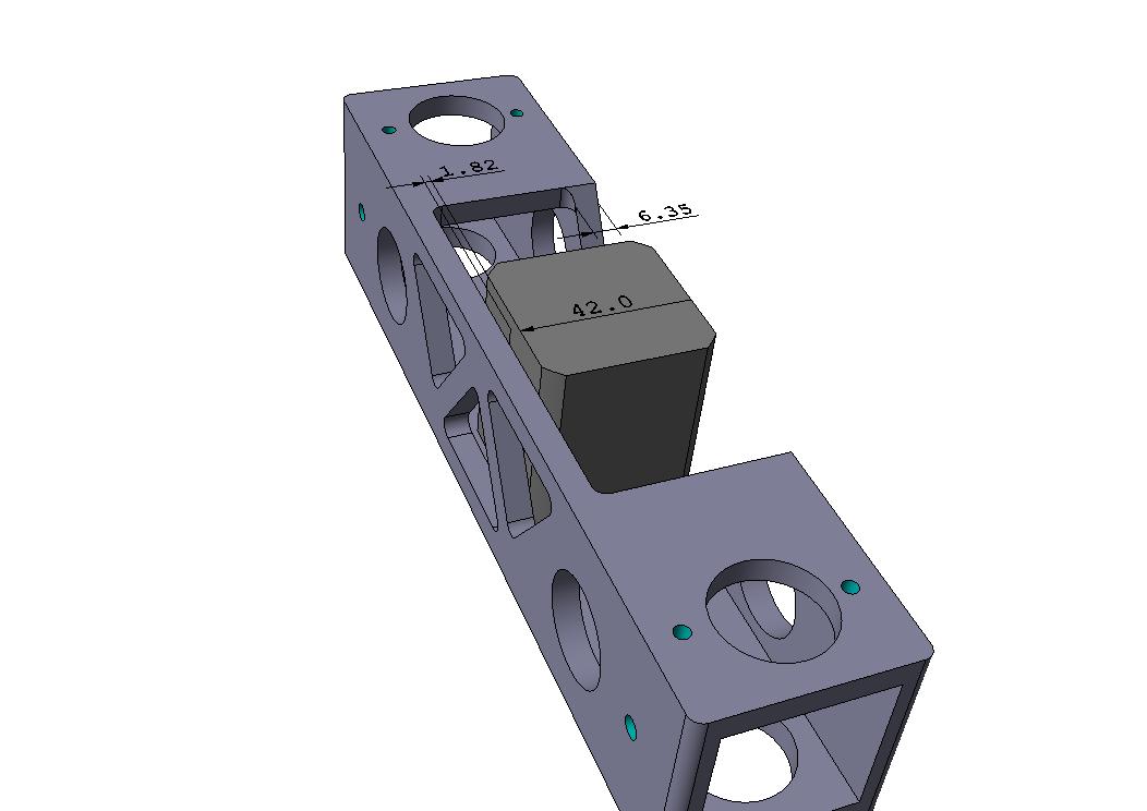
I just uploaded the new .stp and the new .dxf file to Thingiverse
1 Like
I know I can just bookmark this and silently follow this thread then pillage the information for my own benefit - and a great benefit it will be! Rich - amazing upgrade! I just moved homes/States recently and am getting ready to re-build my LR2 and get some projects off the To-Do list.
I wanted to say how nice this forum is to glean some brilliance off of other people’s obstacles. I am an Army Engineer and busting through obstacles are what we are bread/educated to do. You sir, have busted a huge one in my view! Well done! I particularly like the aluminum rails you have for your Y axis - will be stealing that one for myself. I have a table I use that is one I can move around and level out as needed - thanks to Paoson.com - a carpenter out of Barcelona. I have bench edging with a miter gauge slot on top that I can raise and lower as needed. But I will now flip these over to add rails for smooth transit.
A note to Ryan - it’s amazing how a forum like this can support so many makers work through the issues that arrive. Thank you for the platform to mind-meld with others to work through stuff. With the news being to blight for the past 12 years, I’m finding I am more and more cynical about people. But recently I returned to the forums and I find therapy is much cheaper here!
4 Likes
Rich, thank you sir, this it great.
Now I’m obligated to make those
I’m confident I can do it, it’s being nothing but Aluminum cutting for me for last month.
Only thing I have not solved properly is how to consistently find X/Y zero point, which will be critical for this 4 side job.
Not to high jack this thread but any build details on that router mount?
Thank you for your appreciation. I hope my designs work also for other people and that their / your workpieces turn out at least as good as mine
@spacegrey: as I wrote, the most important thing is a rectangular cut on the left side of your square tube. This ensures a consistend reference. For the repeatability at switching the sides, you may carve a pocket in some scrap wood where you could put in and clamp down the aluminium tube. Just an idea if you don’t have the touch plate option…
@RobP: I already posted the mount but I did not publish the files yet because they need some optimisation 
Lowrider2 - router carriage with quick release mod - LowRider CNC / Hardware Development - V1 Engineering Forum
Cheers
Richard
Super cool mods, but I’m going to ask the tough question: What was the improvement in cut quality in the end?
1 Like
Thanks! The cut quality became very precise and fast enough for me
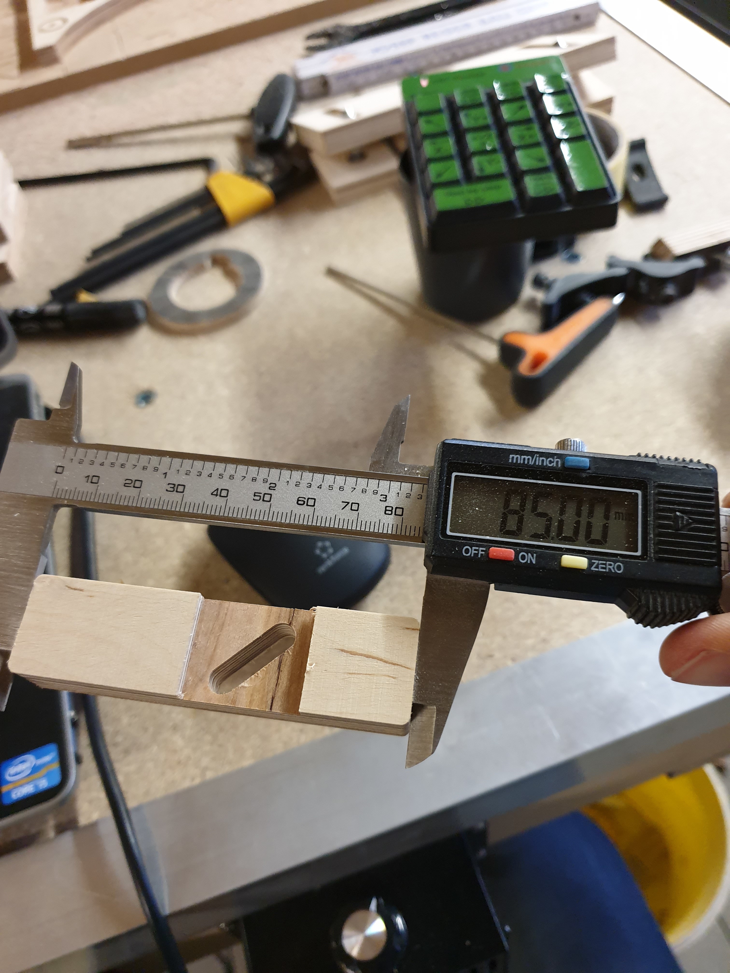
This is just a result some minutes ago: DOC 3mm with 2 flute 3,175mm UpDown Bit, 800 mm/min pre-cut and 600 mm/min finishing pass
Maybe I could go faster
4 Likes
I mean…could be better were you trying to hit 90mm?
1 Like
 nope. exactly 85mm
Dang, now I’m going to have to do this too. Thanks for making my project list longer!
1 Like