I’ve started to put things together at a very slow pace as I still need to source myself with some hardware and need to cut the YZ plates and the strut brace on the LR2…here’s where I have a problem and need some help, my PC crashed and needed a fresh software instal, due to this I’ve lost my feed and speed and tool info, can any of you @jeffeb3@vicious1@SupraGuy or any of the LR2 experts recommend feeds and speeds and depth of cut for MDF on a single flute?
I would appreciate your feedback a lot as I’m stuck at the moment…
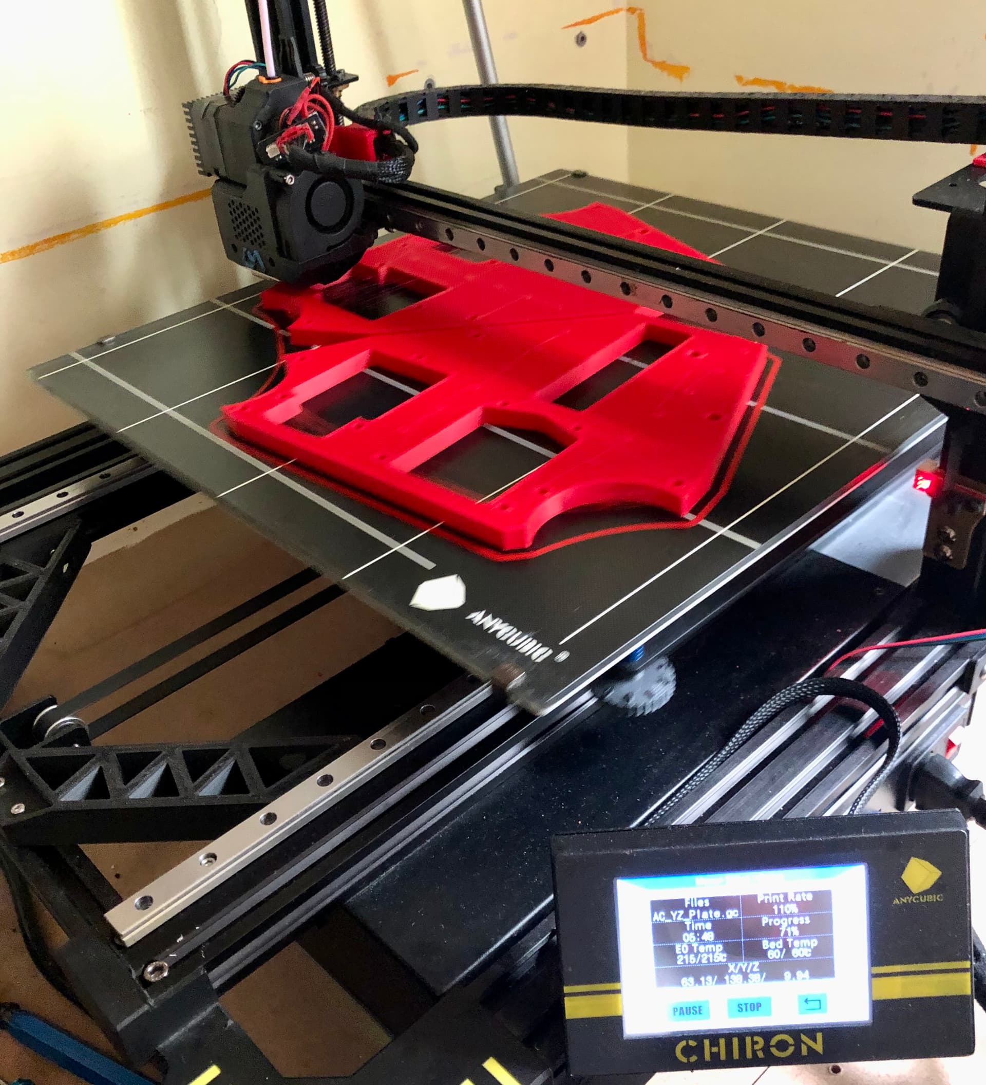
Thanks Ryan. I’ll do so, although I remember going a bit deeper and faster after a few cuts I can’t remember how much faster and deeper…meanwhile I’ve gone mad and I decided to print the parts and see if they can withstand the rigidity test…fingers crossed.
Could you all LR3 builders tell me what conduit wall-size are you using? I’m finding that most of what I can find locally is a 1,5mm wall which I’m not too sure if it’s enough, specially for the X axis.
Thanks Dan, then I’ll go this weekend and source myself with proper tubes…although I need to design my table first as I want to change a few things from the old LR2 and probable go folding and enclosed table…mmm…need a lot of thinking.
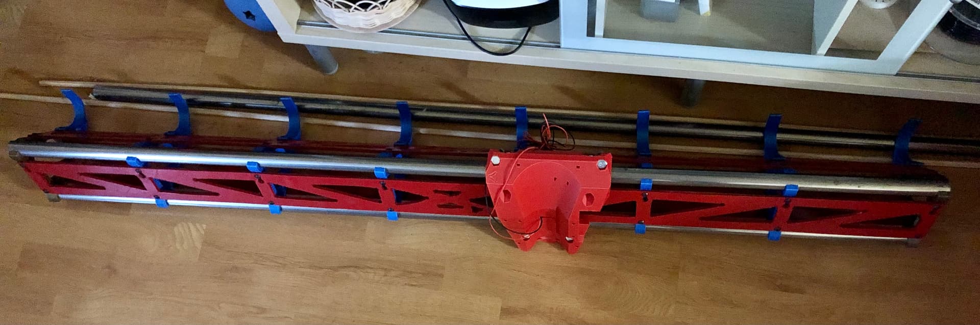
Going slowly but will get there, today I started dismantling the LR2 too…have a table design in my head that needs to go through Fusion360 for real accurate mesures. So far very happy with the new design…great job again @vicious1
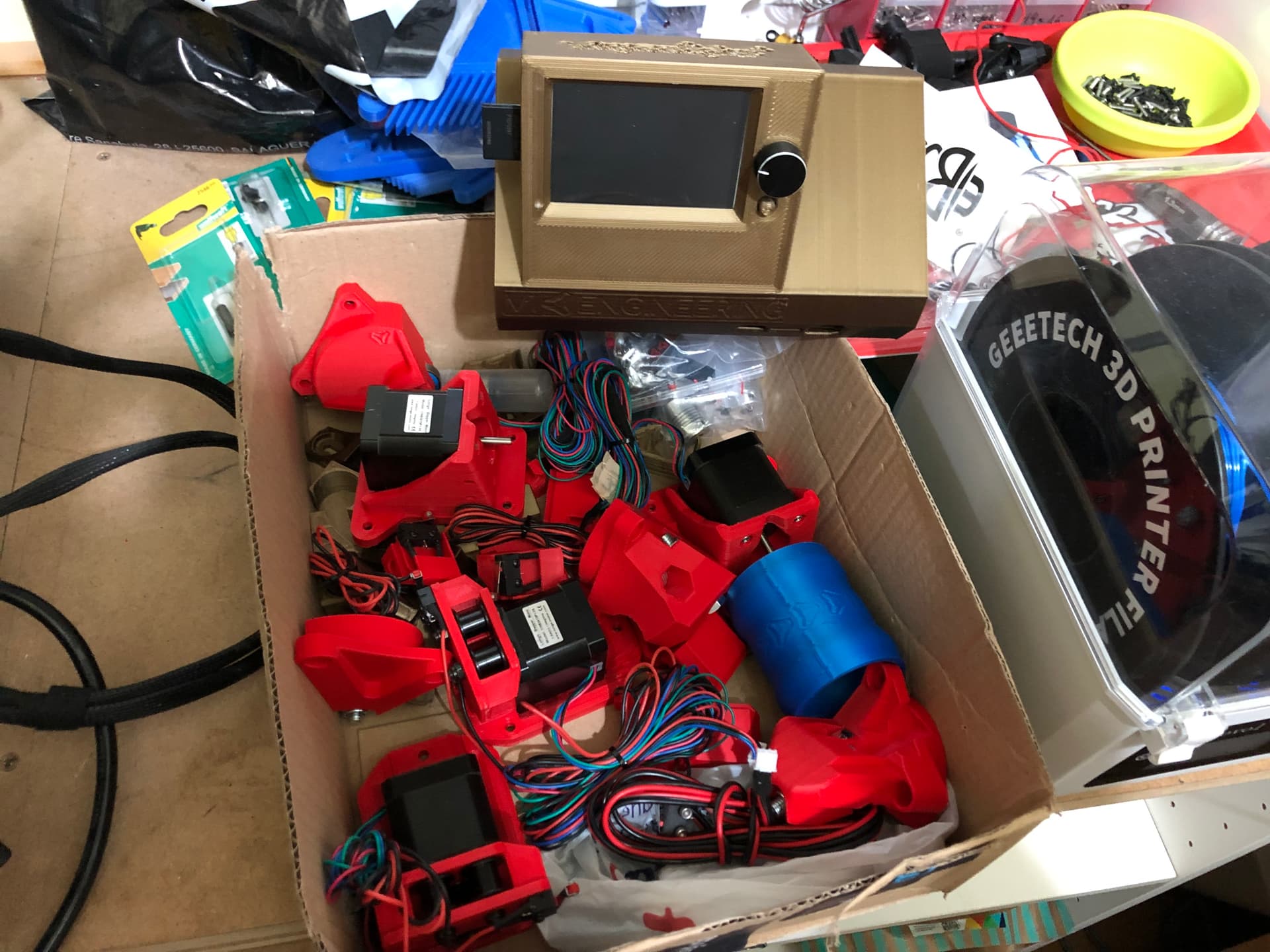
Oh yeah !!! All parts with motors, endstops and pulleys done, now waiting for the linear rails to arrive…meanwhile I’m going to design my folding and enclosed table.
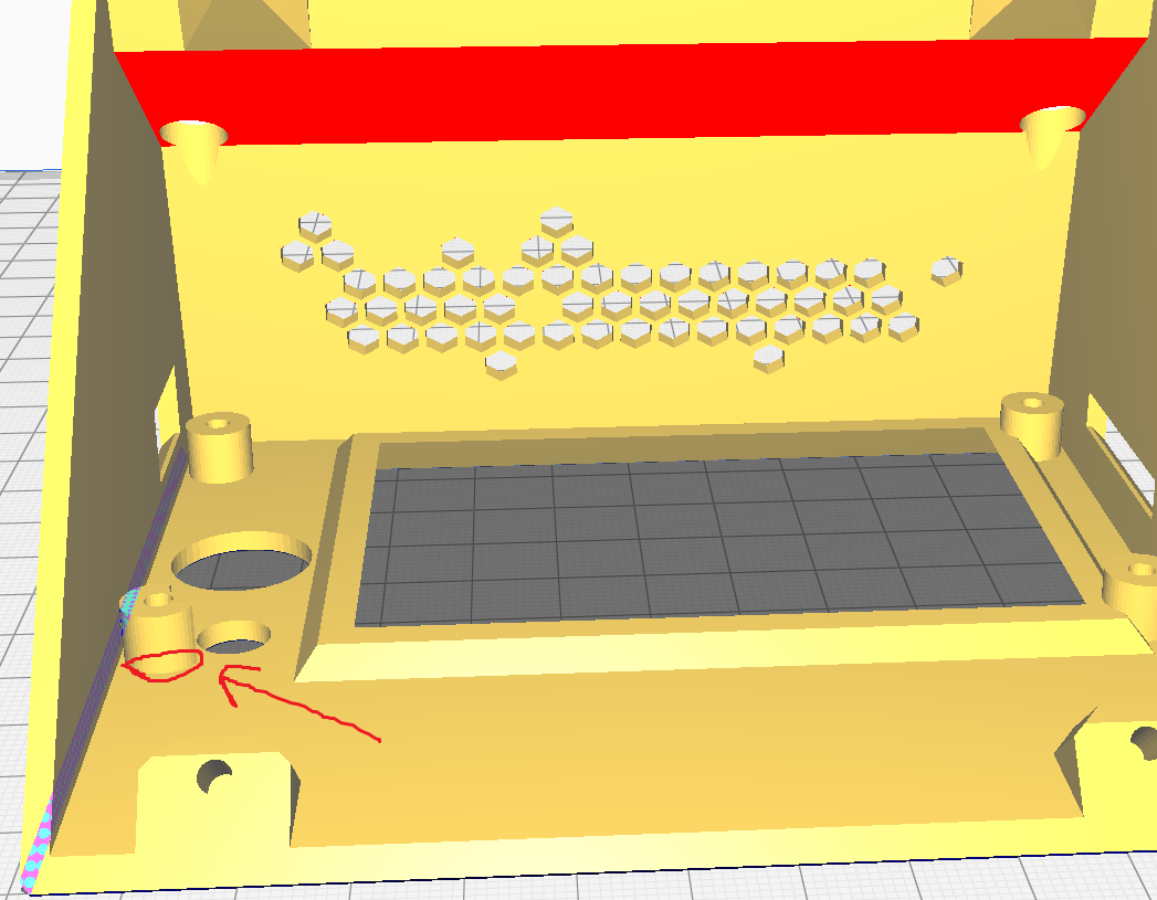
Is there a chance to add a chamfer to the base of the screw taps? I’ve already broken one, my fault for overtightening it…but chamfering might help a bit.
First of all don’t take offence please . I mean adding a chamfer or so where the screw insert meets the box base to hold the SKR board and the Screen. I hope the image helps a bit more than my horrible explanation.
In any case, I’m very happy with the design as it is !!!
Hey, thanks for the clarification. Regarding the instance of breakage due to over tightening, could be that the screw was too long? I’m pondering on breakage versus merely a stripping of the hole out. If I gave a suggested length of screw, and it was that length that was used, and it’s too long, I need to edit my description in the Printables.com link.
Ok people, I’ve been very busy at work and had no spare time to keep on building my LR3. Today I managed to finally put the sides together and bolted them to the X carriage…it looks beautiful !!! At the moment I’m rethinking my foldable -portable table and will probably end up going on Alum 6030 T-slots to get a nice flat, somehow stiff and low-weight table bed.
I can’t tell you at the moment 100% sure, but it could well be me using the wrong screw length, I have some screws mixed up on the 8-10-12 mm lenghts…from previous projects had them wrongly classified in my small screw boxes.