I understand the fan pins use 12V by default. But can be remapped/changed in the firmware to 5V.
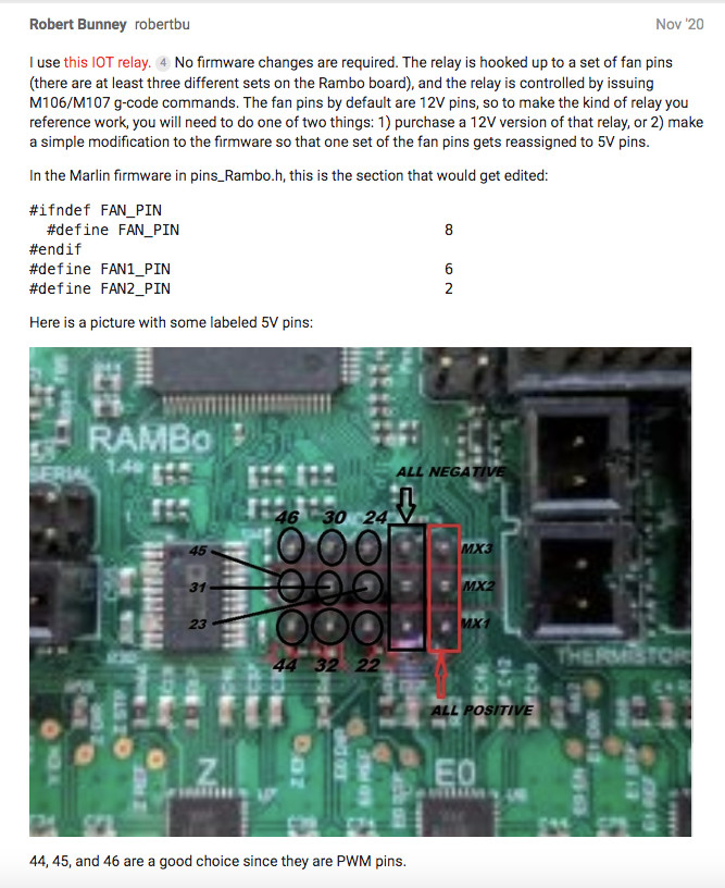
In this post KY-019 relay to control Router there is an explanation I’ve screenshot below.
I’m not clear on which of the pins in the diagram to use. If someone has a better idea of how this could work I’d appreciate any feedback. I’m in the UK and the IOT relay isn’t an option for me.
I would use pin 22. Alternate choices are pin 44 and pin 46. Note that pins 44 and 46 are PWM pins but pin 22 is not. This should not be an issue. Pin 45 is allocated to a laser if you ever install one. The changes are made in Marlin/src/pins/rambo/pins_RAMBO.h.
Personally I selected FAN2 for my IOT relay because it was by itself on the Rambo board.
And I’m sure you would have figured it out, but to save you a step, turning the fan on and off is M106 and M107. The ‘P’ parameter indicates which fan. M106 without a speed (‘S’) parameter turns a pin on full.
M106 P2  ; Turn on second fan pin
M107 P2  ; Turn off the second fan pin
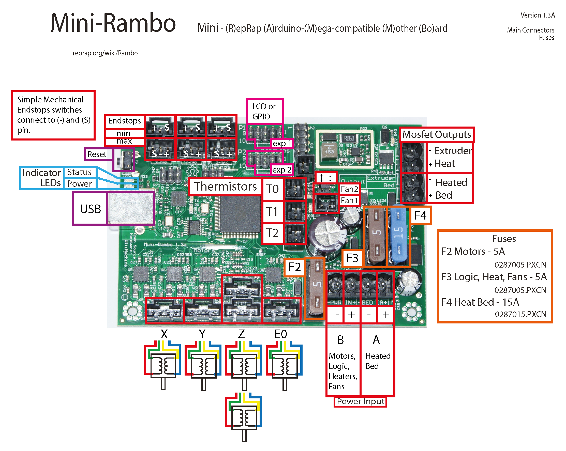
Thanks for replying Robert. I just realised that the diagram is Rambo 1.4 and I’m using a Mini Rambo. Doh! Do you know what pin to use on mini rambo? I’m looking at the board now trying to figure it out.
Do you think the 5V relay would work with a 12V logic signal?
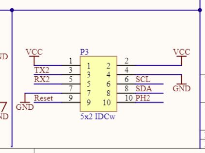
If you look at the picture, just to the right of LCD or GPIO pins is a block of pins marked P3. The schematic for that block looks like this:
I believe (but cannot be absolutely sure), that PH2, RX2 and TX2 are unused for the MPCNC version of the Marlin firmware. The pin numbers mapped to these ids are:
RX2  16
TX2  17
PH2  84
For remapping, I believe you need to change pins_MINIRAMBO.h in this section: