The settings for the V-Bit in Estlcam are still off. 
Did you try again? How did it go?
I haven’t yet but I plan to today since the wife has left town for three days. I relish these days of freedom!
Jerry
4 Likes

2 Likes
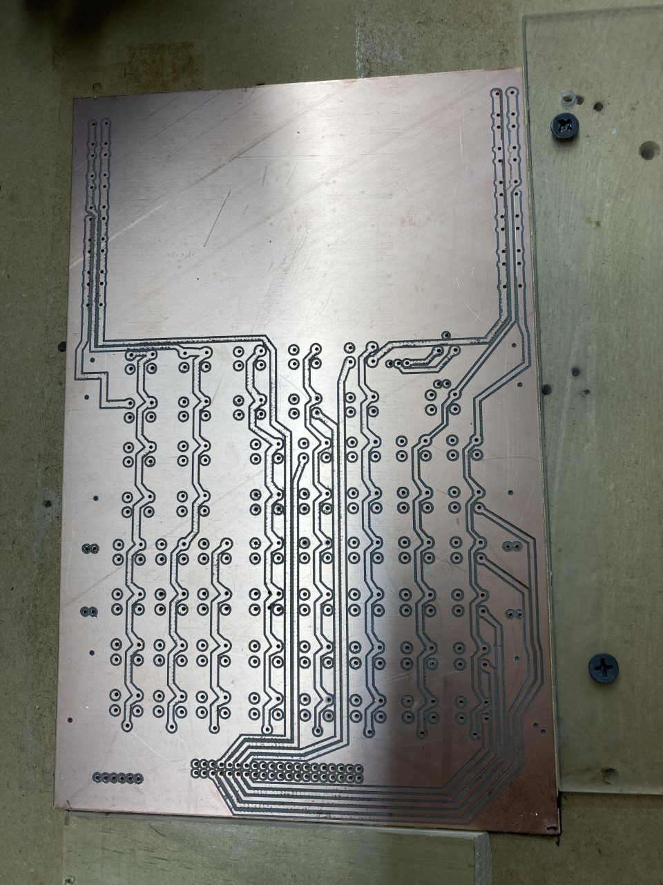
The front side turned out pretty good. The trick is going to be getting the back side to match the holes.
2 Likes
Wow that is good. You know i wish i had said you need reference holes to keep alignment
Maybe you can use the holes for circuits for alignment
I have it in a jig and flipping it over should have kept everything aligned but guess what! When I flipped it over I discovered the board isn’t square. Guess I’m going to need some alignment holes after all. I’m complaining to Amazon.

1 Like
So here, try this set youtr zero in estlcam to one of those holes. The one that is in your lower left corner maybe. Set your bit in that hole. I think you will be good.
That would work for getting a zero point, but you would have to make sure it is square with the machine (or at least the region being cut since the pcb isn’t squared). But even a few degrees would probably be enough to misalign the holes.
After working to one hole, if you can then place a pin in the hole to pivot on your should be able to move the bit to the furthest hole (for best angular accuracy) and adjust the angle of the board to match the position the machine thinks it should be in.
I’ll try that today. The problem is when I flip the board over I’m working from the opposite side so zero isn’t at the corner of the board since its out of square.
Jerry
1 Like
But here, I am trying to paint a picture with words.
When you flip the drawing, choose a through hole that is in the diagram. make sure your board is aligned with the way you put the pic into estlcam and then choose that through hole to align too.
Are ALL sides out of wack, or only the one. If only the one, you can aling to one side. Set your zero to that hole in your diagram and you SHOULD be ok.
Make sense???
The top and bottom are out of square, the sides are good although the board was supposed to be 150mm x 230mm. The width is 148mm so uxcell got it too narrow. That accounts for why my traces on the back side were slightly off. I did what you said and chose a hole at the top and bottom. Then I looked at my gcode to see exactly how far from zero those were. Then I moved my bit to each of those points to get the board positioned right and drilled a hole and put a pin in them. It worked pretty well although slightly off. I wish Repetier-Host would allow you to move the x & y axis .01mm. Then I could have gotten it exact but I believe its close enough to work. The back side wasn’t quite as clean as the front and I didn’t cut quite deep enough on a few engraves so I had to Isolate them in estlcam, make a correction file and wedge under the board and do a re-cut.
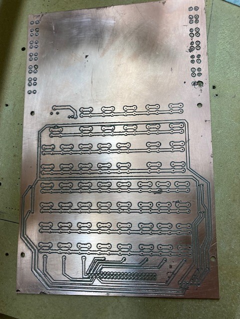
Awesome. Not quite my intention, but got the job done. I was saying to change your zero point in estlcam. Then re export gcode. But hey good job!
1 Like