I am using F-engrave to create some inlays. I created the files and saved to sd card and fired up the mpcnc. What I get is about a dozen or 2 very small moves and then the router just stays in the same place…forever.
I uploaded the files to NC Viewer and the tool paths are all there. I emailed Scorch and he didn’t see anything wrong. I then loaded and old file, not v-carve, and it worked fine. I am at a loss.
The files come out of F-engrave as .ngc but those files are not recognized by my machine (Rambo 1.4) using the Large Smart LCD controller, so I saved them as .gcode.
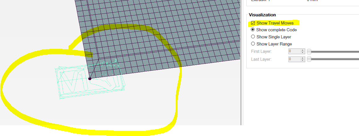
I loaded the files in Repetier Host and the gcode is there, but nothing shows in the 3d view, not even tool paths.
I loaded up that gcode into Estlcam, and it looked like a V1 logo carve to me.
Repetier host may be looking for extrude commands for things to show, so that it doesn’t show “non-print” moves, in which case, this will show nothing, since there is no extrusion.
There is some g-code that is not supported by Marlin
The coordinates are in inches, and by default, the V1 maintained firmware does not support inches.
There are no feedrate settings for any of the moves.
So for #1, at the top of the file are these lines:
G17 G64 P0.001 M3 S3000
F5.00
There is some weird CR/LF associated with these two lines. G64 is not recognized by Marlin firmware. And I’m not sure the G17 is the same for Marlin. I would just comment these lines out.
Issue #2 can be resolved by either setting the units to mm in F-engrave, or by enabling inches as units in the firmware. F-engrave may allow you to author in inches but output your g-code in mm. Both EstlCam and Fusion 360 allow this separation between authoring and g-code generation. If you want to work with g-code in inches, you need to uncomment the following line in configuration.h in Marlin and reflash the firmware:
//#define INCH_MODE_SUPPORT
Lastly, you need to establish some feedrate for your cutting. Adding an F parameter to one of the first G0 or G1 commands will do the job.
What I get is about a dozen or 2 very small moves
Just to be clear, the moves are the entire engraving done at 1/25.4 scale and very fast due to a lack of feedrate settings.
Thank you all, I made recommended changes and got what I was looking for. Now for fine tuning.
The 2 halves do not fit together well, very loose.
60 degree bit 1/2 diameter, what should I be using for max cut depth? It was obvious that the carvings were to wide, lost definition, looked like ballooning of the outline.
Also, I need to make a tool change for end mill for clean up, how to I make sure I’m still in position? My test run last night was lightly off. If I run the router over clear of the work piece, do I need to go to my origin point before starting or will the router return to the correct place?
The exact tool change process will vary depending on your authoring and sending solutions. Leaving the steppers engaged during the tool change is the major magic ingredient. Personally I:
Author all tool change runs as separate g-code files
Always leave the steppers engaged and move the router electronically during a tool change
Use a touch plate to rehome the Z axis after a bit change
Always return the router to (0,0,0) before running the next file.
When using the top of the stock as Z reference, #3 can be a problem in some situations like relief carvings. In that case I use the spoil board and the height of my stock to reset my Z home position.
As mentioned, these steps may be different depending on your pipeline. For example if you don’t execute a G92 at the start of your run to reset the home position, #4 is not necessary.