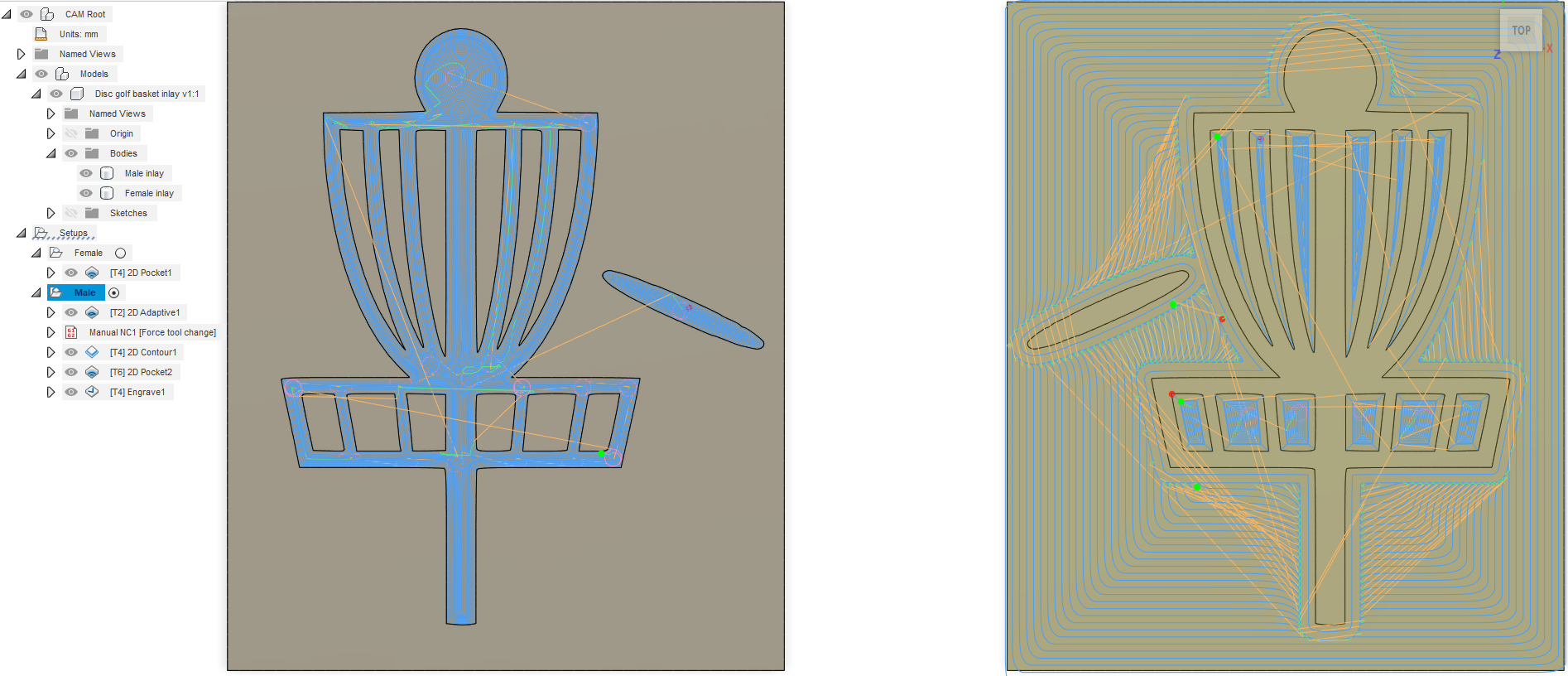
After having some success with the excellent tutorial by @ianj001 , I decided to have a go at doing this with fusion. Here’s some info on how to do it… unfortunately not a full blown tutorial. I find the cut times for me were about 4x faster and also it supports those v-groove bits with the flat bottoms so I’ve got some on order since at least for the female parts it would mean better cleanup without changing bits.
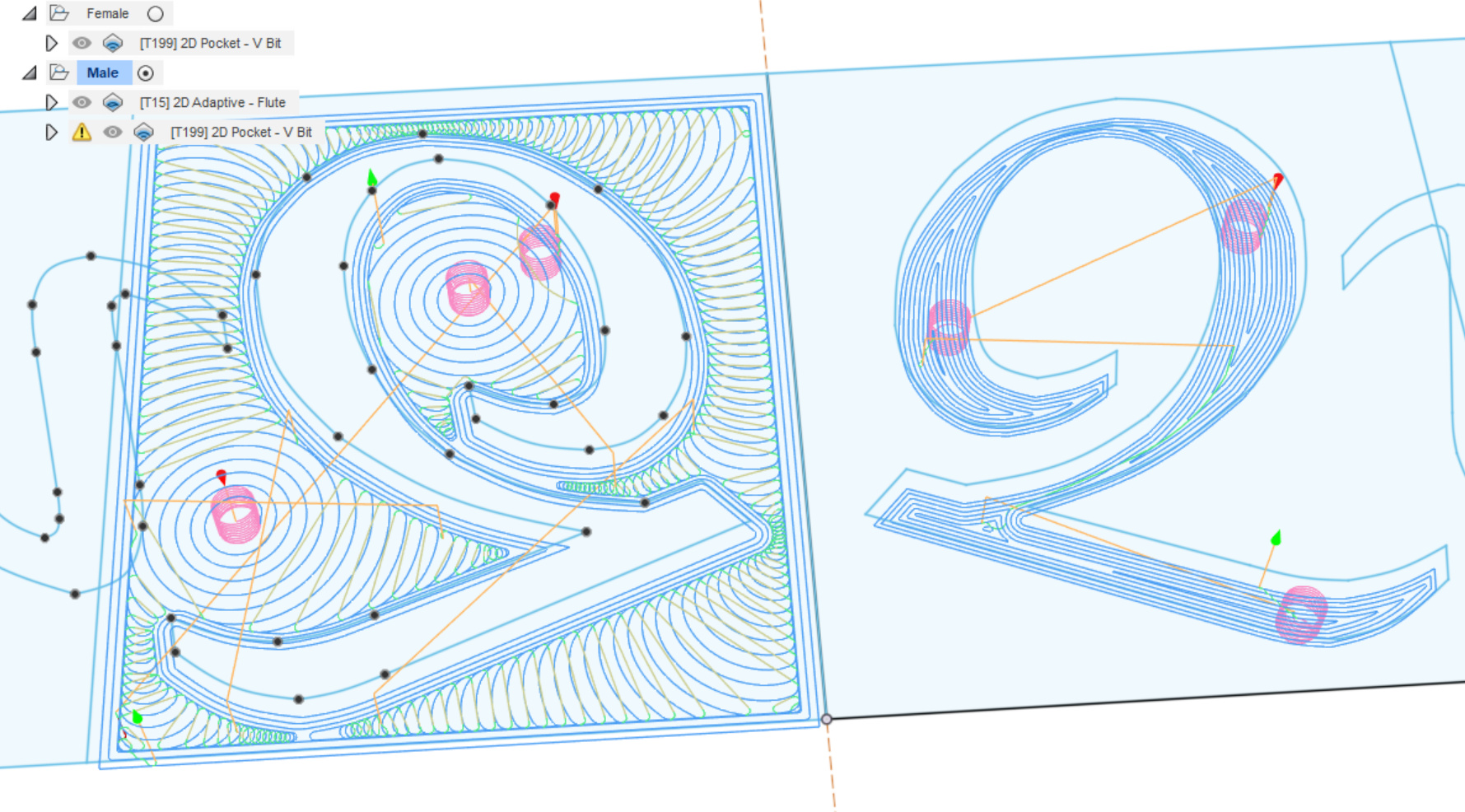
I started out making a sketch, adding some text with the text tool, then picked ‘explode text’, then using the mirror command to mirror it.
After that it was:
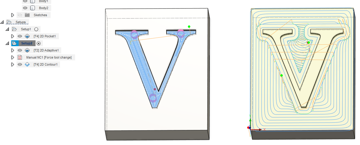
Female - Right: 1) 2D pocket with V-Groove bit ( I used 30 degree)
Male - Left : 1) 2d Adaptive with a 1/8" fluted bit then 2) 2d Pocket with the V-groove bit
For all the paths, I set the bottom height to -2mm from stock top
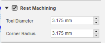
For the male V bit pocket, I set this value so it didn’t try to re-do any of the cleared areas:
Note that it doesn’t matter which order you do the male cuts. You can do the pocket first then the adaptive and it still works.
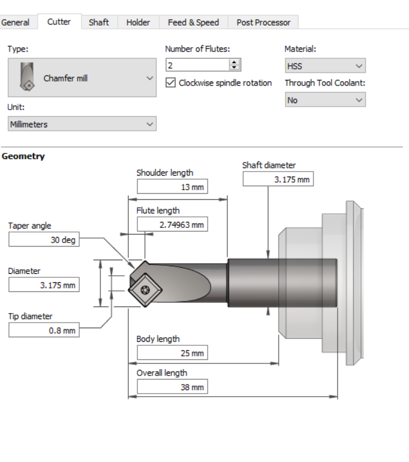
Now the secret suace… by default it will try to do the V cleanup with the 0.1mm tip on your bit which will take FOREVER. I ordered some new bits with 0.5mm and 1.5mm tips to play with, but in the meantime we can cheat and just tell it we have a fatter tip. You may wind up with some ridges depending how hard your wood is and how fat you set the fake tip. I set mine to 0.8mm and it went pretty fast but the bottom wasn’t perfect. Maybe 0.5mm would be cleaner.
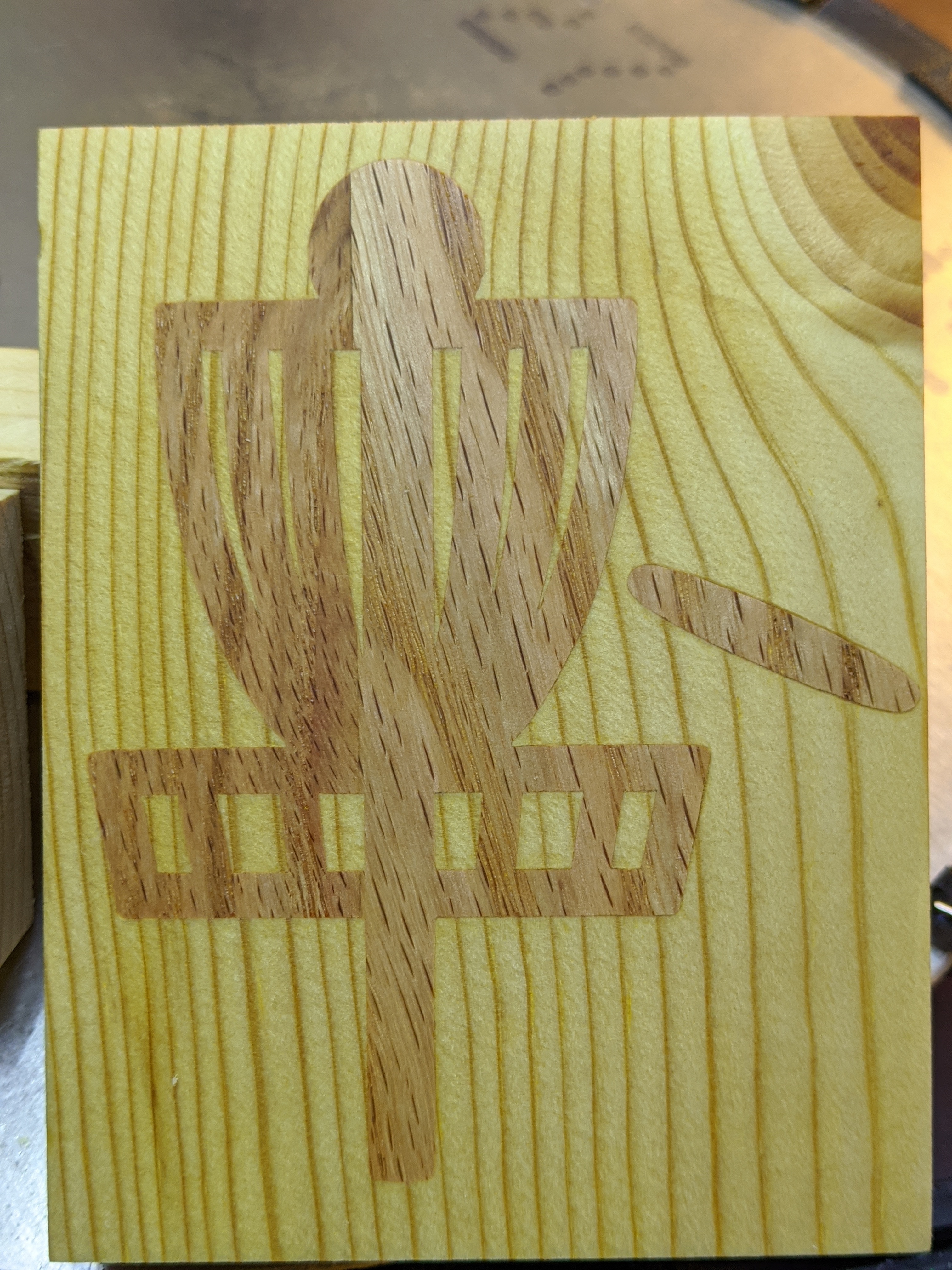
If you want a tighter or looser fit you can adjust the ‘stock to leave’ on the two male toolpaths. Positive will make it tigher, negative will make it looser. May try a very small value on my next run like 0.05mm just to leave a small gap for glue at the bottom and apply some extra pressure on the sides. Without any offset I was able to get the male and female pieces to meet flush when I put them in my vise for glue up.
I will definitely revisit fusion for this. If you look at my post that is what it started out with but I had some issues getting fusion to work properly. I will follow what you have done and see how that goes. I will make a video of it so you can see if I am successful or where I go wrong. - My first fusion attempts were close to be fair but the F-Engrave just seemed easier to produce the code however, I am a big Fusion 360 fan.
I should also say, I like the MDF idea, I will give that go too, its a good contrast to the pine and other white wood I have.
The work speaks for itself but I am still curious, wouldn’t it mean you have crisp outside corners but rounded inside corners? And it would in theory mash the pointy outside corners into the blunt inside corners where there is a small interference?
In a totally different direction, one thing I noticed when trying to make tight interlocking fingers, was the effective diameter of the bit was not the nominal value and it varied when I removed and reinstalled the bit, so I am guessing runout but not 100% sure. But I observed that the pitch from one finger to the next was basically perfect, but the fingers were fat and the gaps were narrow, or vice versa. And this was with a thin finishing pass. By making one test cut and then punching in the implied diameter, I could get fingers that fit nicely with each other. It also made me wonder whether something similar happens with the inlay where the diameter vs. depth is not quite right and the pieces can bottom out before the edges become snug. It’s trickier to measure the tapered walls compared to a box joint, and also unclear if it’s worth it, but maybe.
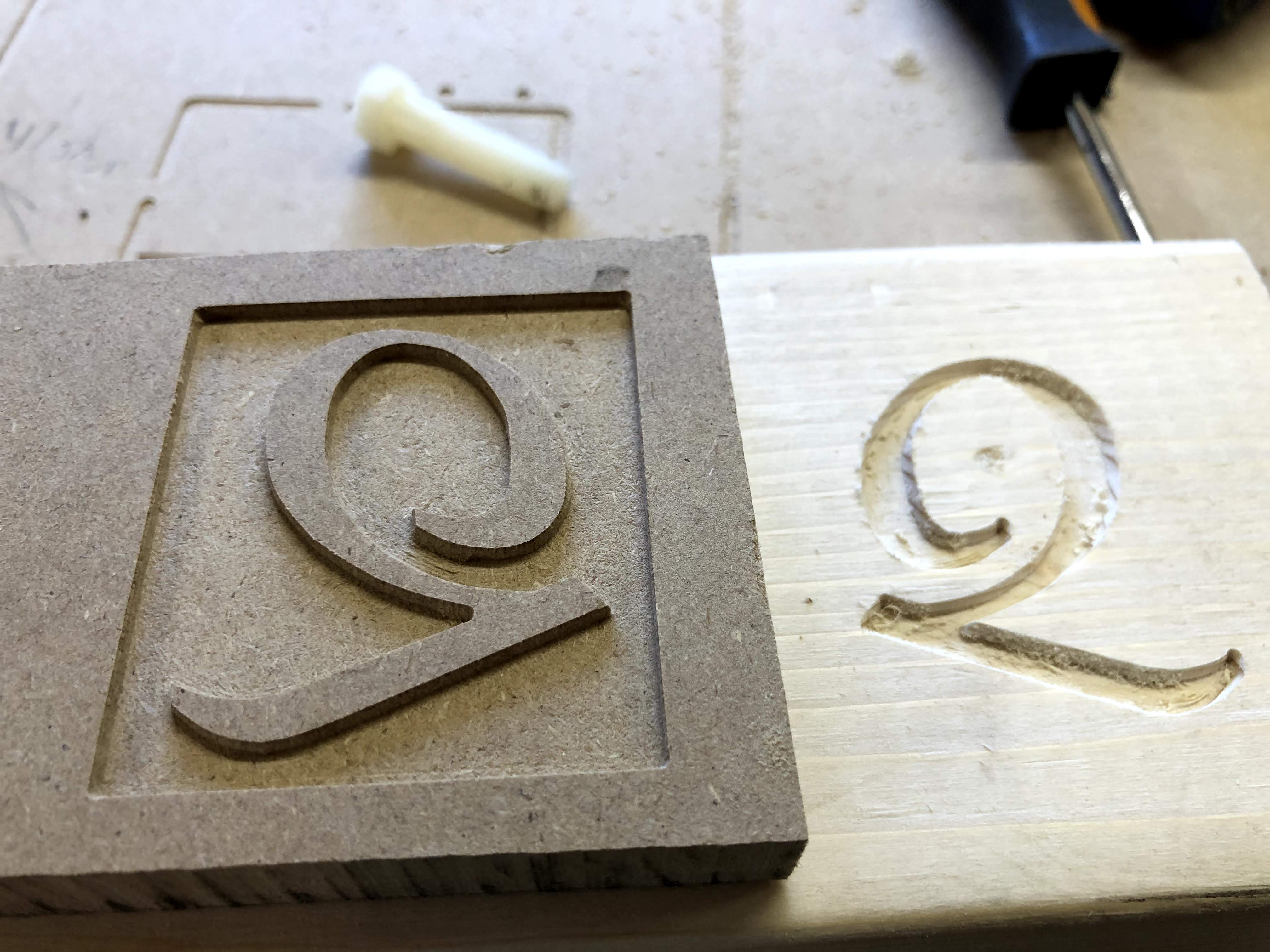
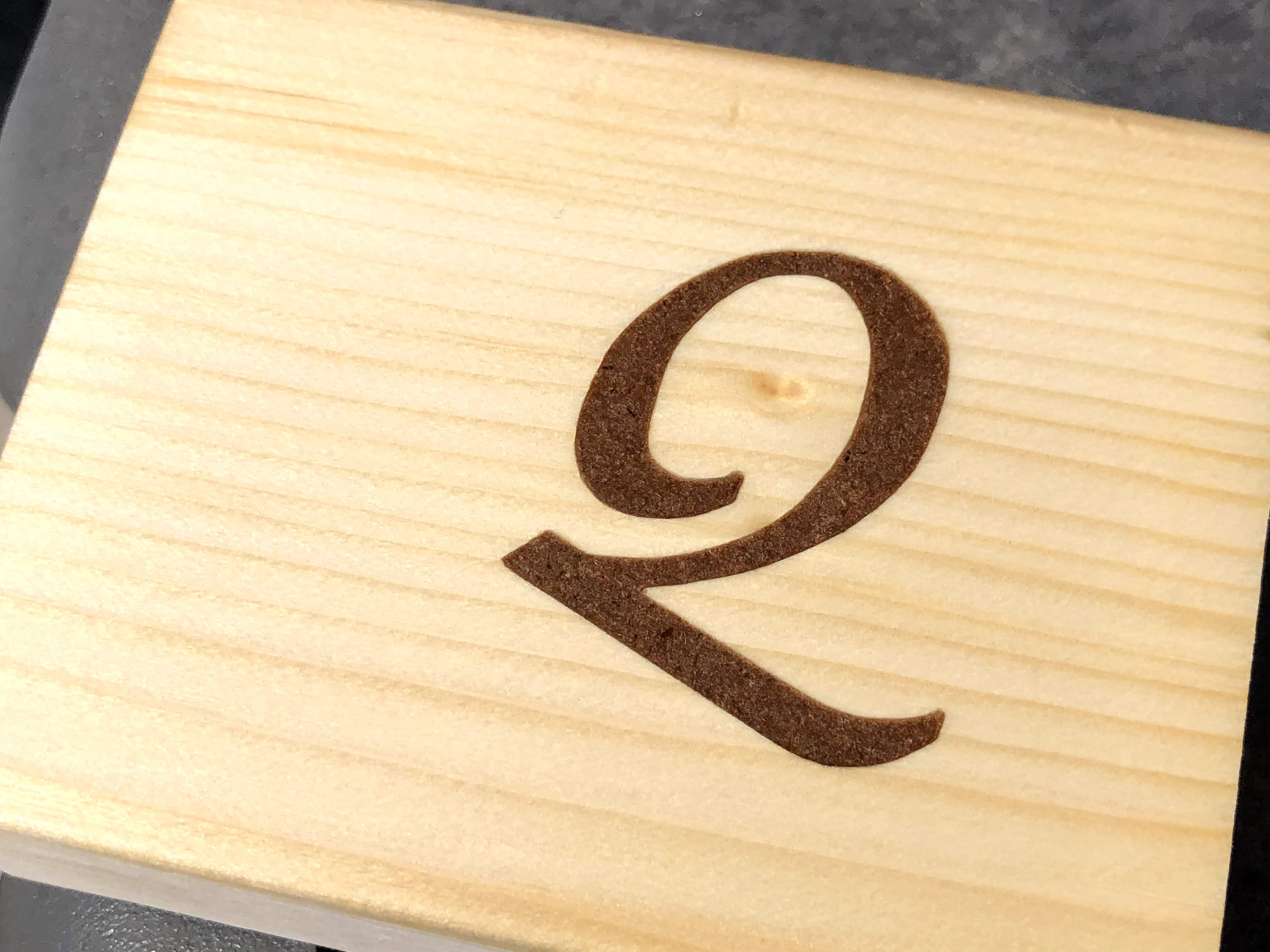
Good point… if you look at the second last picture you can see the inside cut of the Q is rounded on the inside of the tail on one piece and angled on the other. I can’t really see any imperfections looking at the finished piece though. Maybe it would cause problems on a harder wood? I’m curious if this is an issue with F-Engrave or if it automatically rounds the corners to avoid this. Fusion 360 does have a scripting API I’m guessing it would be possible to make a script to automatically round the corners… you can also manually round them pretty easy with the fillet command in sketch you can just type in the radius you want or even bind it to a configuration setting and change them all at once later.
I haven’t noticed the effective diameter of my bits varying at all when I replace straight flutes… it’s kind of a hard thing to measure with the v bits though.
I tested this out, I think it works pretty well, if you want to see how it turned out I have created a video vcarve inlay using Fusion 360 take a look and let me know what you think of the result.
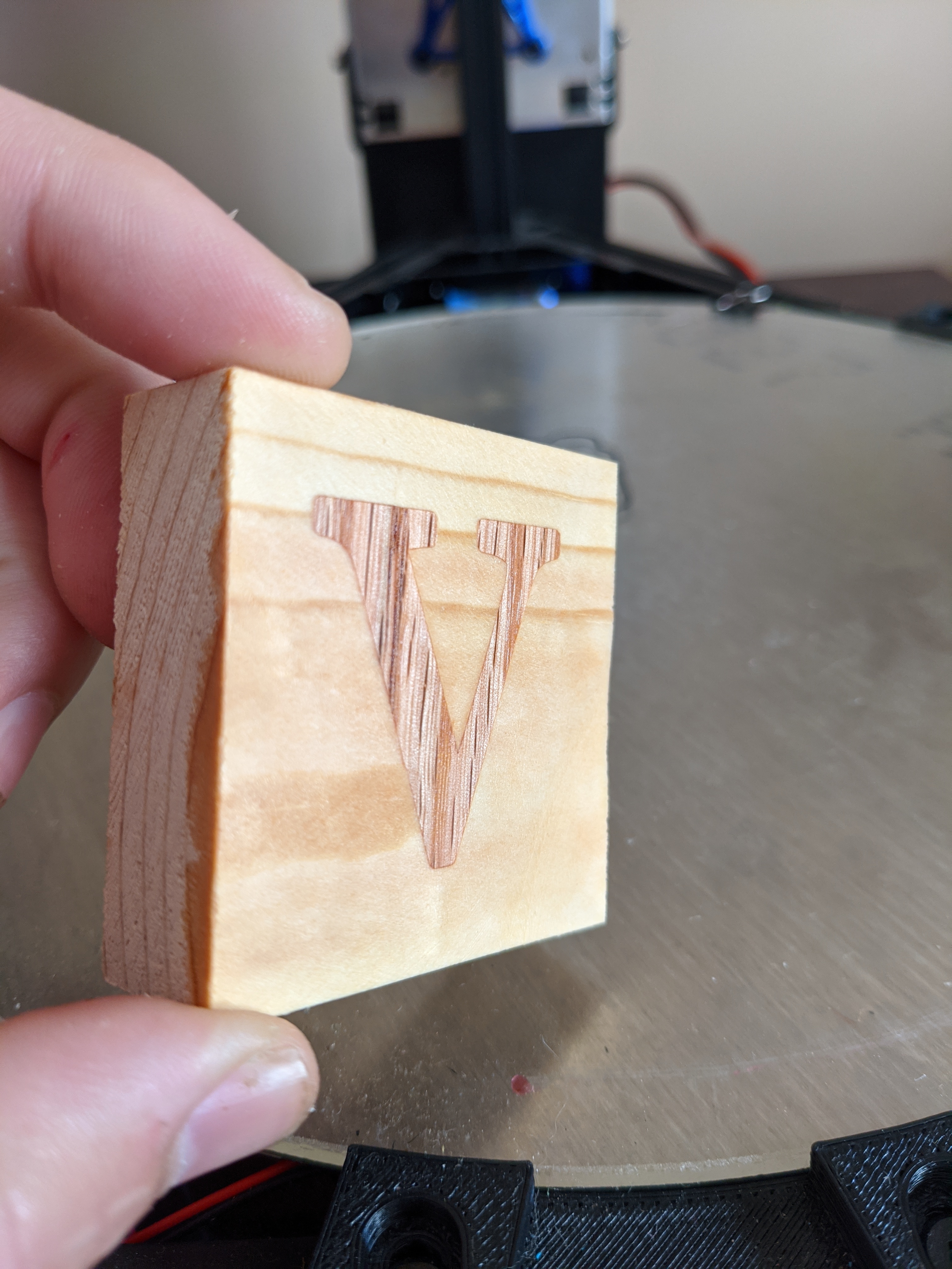
I tried following the method above and the video but was having problems getting a tight fit. So for the male part, I used 2d contour after the adaptive path. Contour seems like a more straight forward method vs tricking 2d pocket. Is there a reason to use one vs the other?
2d pocket with the rest machining set will get all the spots the straight bit was unable to get. 2d contour just follows the contours. So while it works in this case you will want to simulate and check for bits of material sticking up in narrow spots since that is a possibility with this approach. Do you have a photo of the one that didn’t fit tight ?
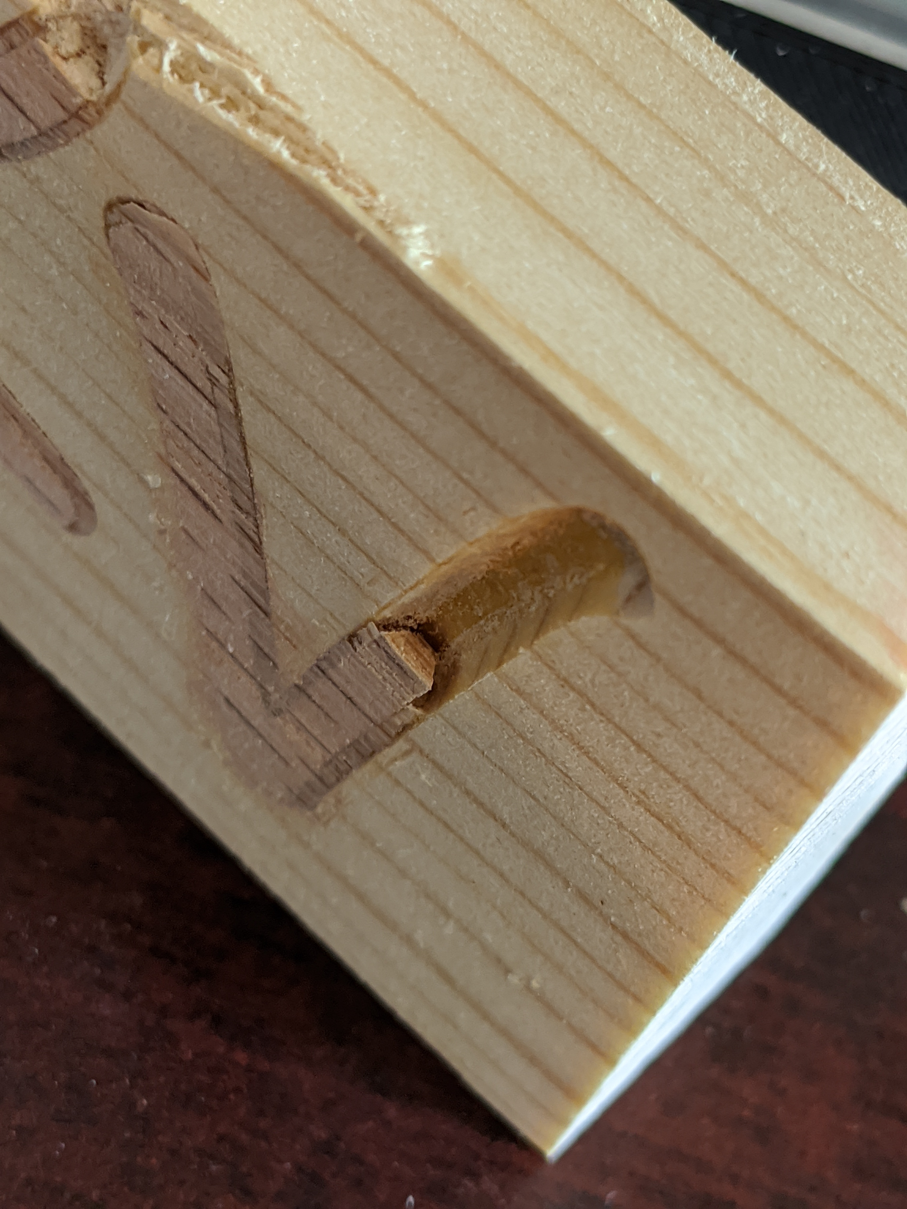
I didn’t clean up the piece as much but you can kind of see the gap between the male inlay and the female part. The glue filled that gap but it was significant enough that the part had lots of wiggle room prior to glue up.
Using the contour method and setting the radial stock to leave of 1.155mm (based on a 60 degree v-cut at a 2mm depth), gave a nice snug fit. There were a few spots leftover but they popped off easily with a chisel.
I’ll dissect my sample piece with the bandsaw later. I’m curious if it’s a problem with both our pieces or if something was different on your setup. I didn’t really feel any wiggle room on mine but it might have been because of the shape.
Tried a more complicated inlay but it forced me to add a few different cutting techniques on the male piece to get everything to be flush. Used adaptive to clear everything on the outside, followed by contour for the perimeter of the basket and disc, then the pocket technique with radial stock to leave for the interior cuts, and then engrave to make the corners crisp on the interior basket points.