A few weeks ago a customer at work I know gave me his 10+ year old laptop full of software he used to use for cnc since he no longer does it anymore. Most of it is completely useless to me as it was not for wood carving in a garage with a homemade machine. However, there is an old copy of Vectric V-Carve Pro installed on it that I’ve used to successfully cut out some vectors with the default 1/4" and 1/8" end mill settings for a few simple signs and everything turned out perfect.
The problem is:
This is my first attempt at carving a 3d toolpath.
When I run the simulation after making a 3D finish toolpath the simulation comes out with rough spiky spots all over it. It doesn’t matter if I use the default engraving bit or enter my own settings for my own carving bits the spikes just won’t go away. The model or method of creation don’t seem to matter and using the model smooth button has no effect either. I’ve even tried changing the stepover value. Nothing works. (I can upload pics if needed)
My questions are…
Are these spikes just visual limitations of the software that will not appear in the final product or are these going to be there if I run this code?
How do you avoid these spikes ruining your work and how do you deal with them before or after you’ve made something?
Is there any better software for 3d carving either free or paid?
I’ve tried contacting Vectric but because this is registered under the customers name and not to me they won’t help. This seems to be really good software and if I can figure out this issue I will definitely be buying it, not only for access to all the awesome clipart they have but so I can install it to another computer besides this slow a** POS laptop it’s on.
That’s not it. I’ve done that successfully.
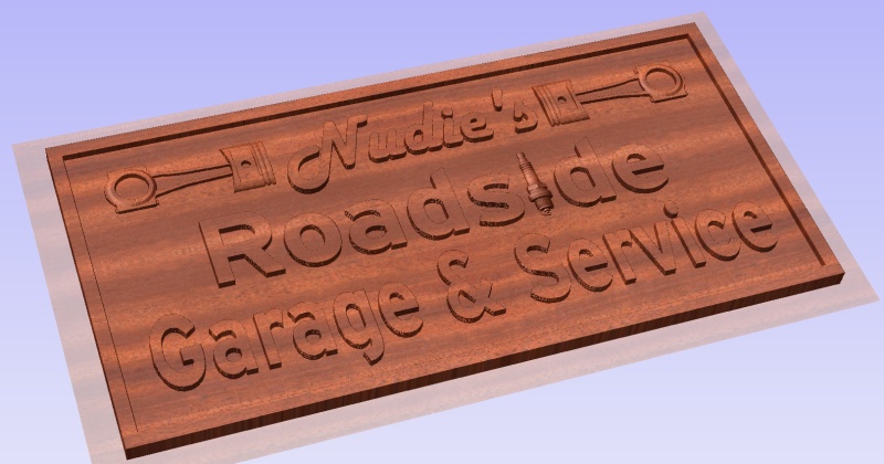
I’m creating a sign that can be made mostly with vectors but it has a few 3d shaped elements.
I just can’t figure how to cut it out.
Here is the model .stl I made in Blender then imported into V-Carve:
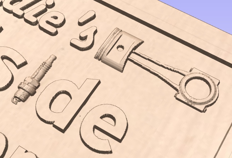
Here it is after creating the g-code and running a simulated cut. You can see on the spark plug and around the piston and one of the piston ring grooves is filled with these “glitches” that are being missed by the tool path. I don’t know if they’ll be in the final product or not and if so how to deal with them and make them less apparent.
I LOVE VcarvePro and find that the 3D simulation renderings are quite accurate. If you see glitches there, you will see them in your wood, too. I suspect this is due to having too course a stepover (set when you choose your cutter). Also, in Job Setup, choose the finest resolution for the model. For any 3D carving that you want good detail, as with this one, you should be around 10-15% stepover on a pretty small bit, like 1.5mm or 1/32" ball-nosed taper. Yes, that will take hours to carve, but that is what it takes to get a good 3D carving, like my terrain carvings.
On the plus side, with such a small stepover, you don’t need to do a roughing pass and you can push the taper bit quite fast (I routinely use 100mm/sec).
You can save a lot of time by using the offset drawing tool to make borders around all the tricky 3D stuff and just apply the small stepover and fine bit to carve inside those areas. Carve the lettering with a much less detailed toolpath. And pocket out all the flat areas with a big flat endmill.
I’ve only had the Vcarve for like 3 weeks now and know nothing about it but I did set the modeling resolution to very high. Just the little bit of playing around with Vcarve I’ve done and I really like it compared to all the other methods I’ve used. It seems to be a pretty powerful all-in-one program.
So what would be the best way to go about making this? I made the .stl in blender but I couldn’t figure out how to break down the different elements to machine them differently so I created 2 rough passes and 1 finish path for the whole thing. Would it be better to create the main parts in Vcarve and just import the 3d elements separately? I tried doing it that way first but it didn’t recognize the 3d parts were there and would cut them off whenever I did a pocket. Offset drawing tool? Sounds interesting. I’m going to have to look in to that.
I’m guessing that If the defects are not in the imported model my model is fine and it’s all in my tool settings. The stepover I’ve tried everything between 5% and 15%. I’m starting to think I might be trying to use too fine of a bit. I have these and I’m trying to use the smallest one. https://www.amazon.com/gp/product/B01N7S00BH/ref=ppx_yo_dt_b_asin_title_o01_s00?ie=UTF8&psc=1
I’m going to try it later with the other bits and see if I can get better results.
Yes, I would import and place each 3D model item separately, and do all the lettering with VcarvePro’s text tool. I would only use a 3D model if that component has some non-flat 3D features to it. Anything that is flat (known as 2.5D) can be more easily done by just setting different depths in your toolpaths. Watch the tutorials that Vectric has prepared. They are excellent and will give you most of all you need to know on strategies for jobs like this.
Also very helpful is Mark Lindsay CNC. He has great tutorials for VcarvePro, and does a livestream every Sunday where you can ask him questions.