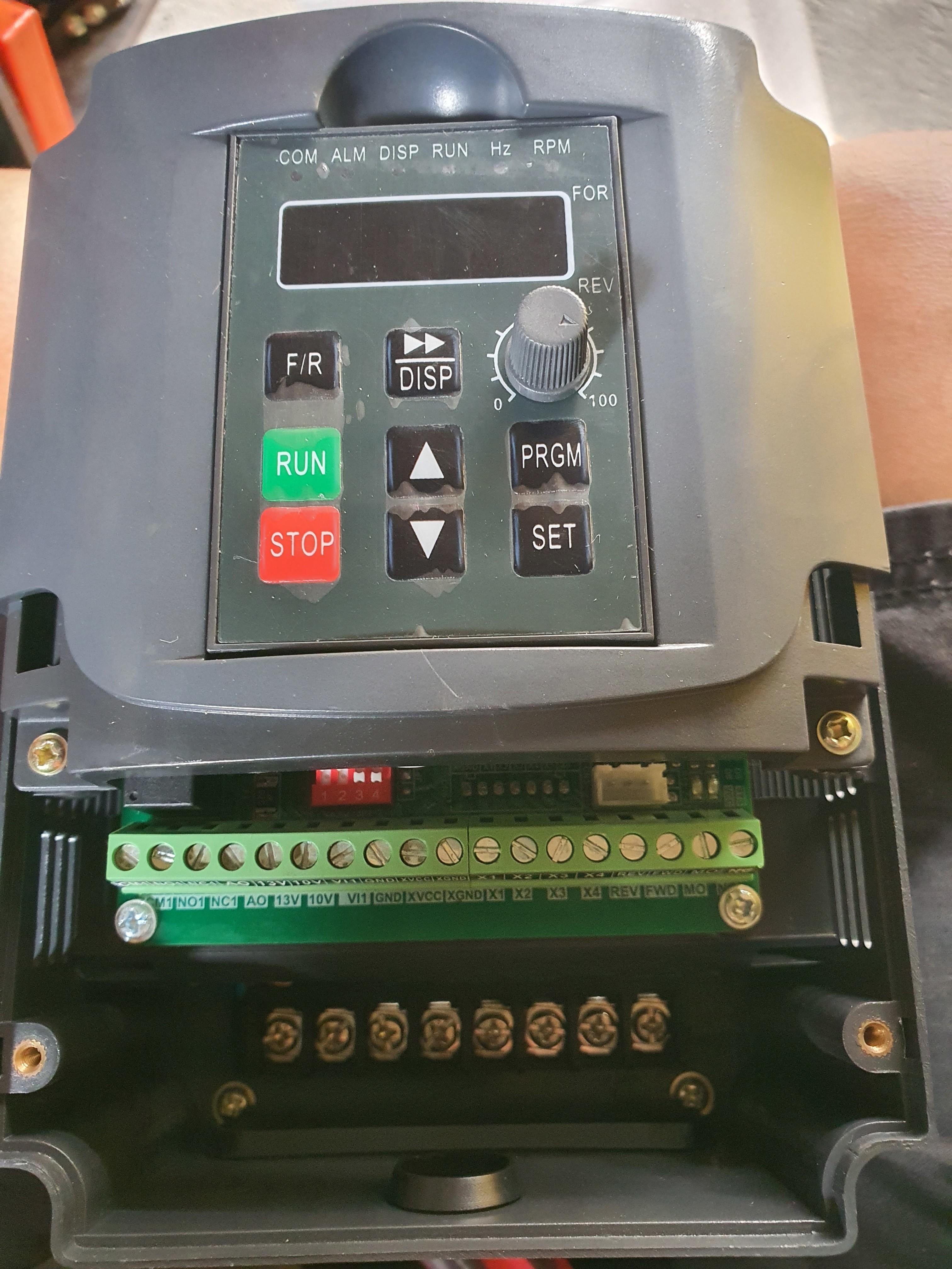
Hi! I just bought a chinese watercooled 800w spindle with vfd but no manual included. I need help wiring it with my rambo v1.4
Any model or manufacturer names on that vfd?
1 Like
I would say there is a lot of potential for something going wrong without a manual, even if you get it running there will be a lot of settings you might find useful. Can you post a link to where you bought it from and have you messaged the seller about some documentation?
2 Likes
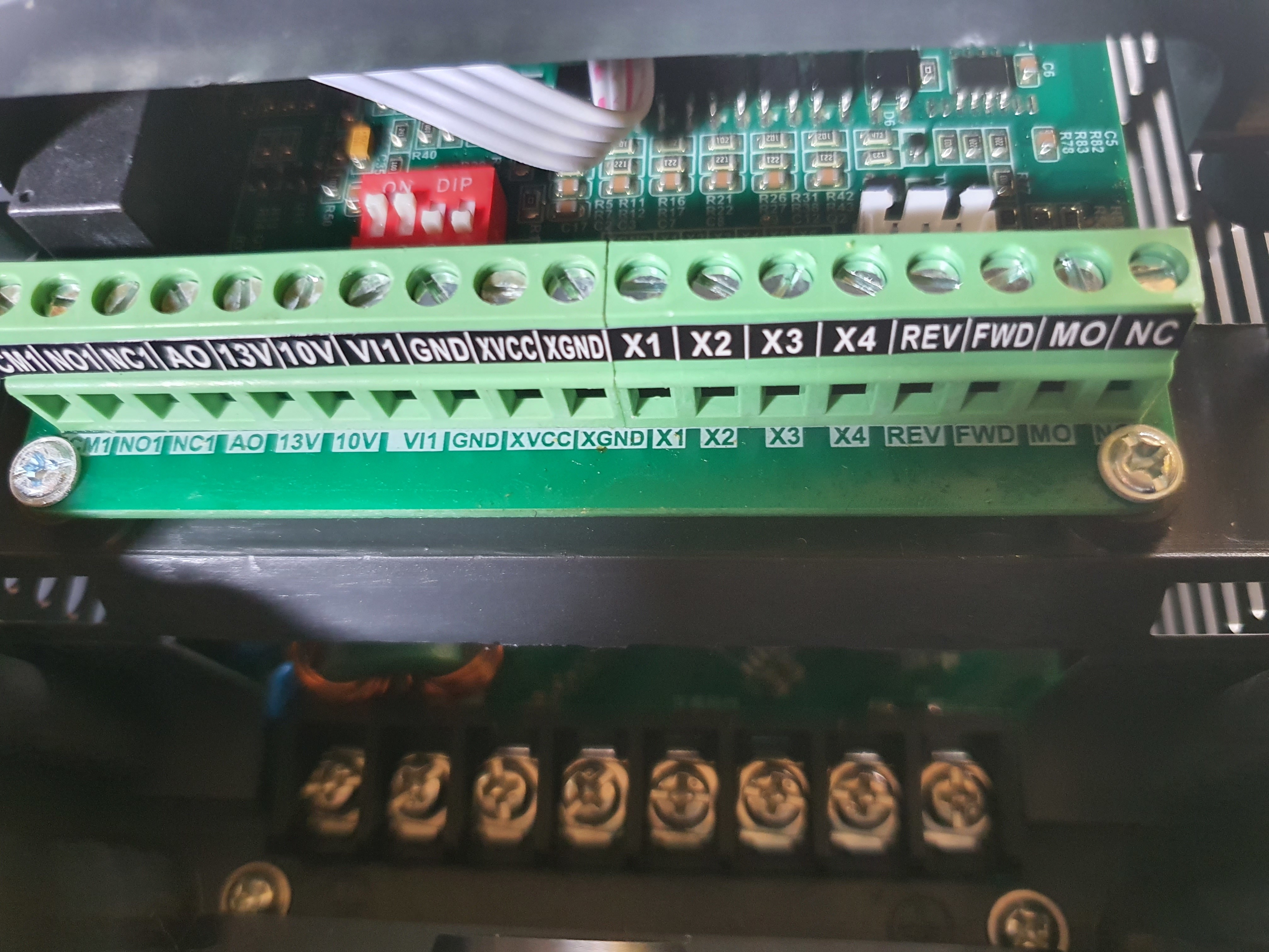
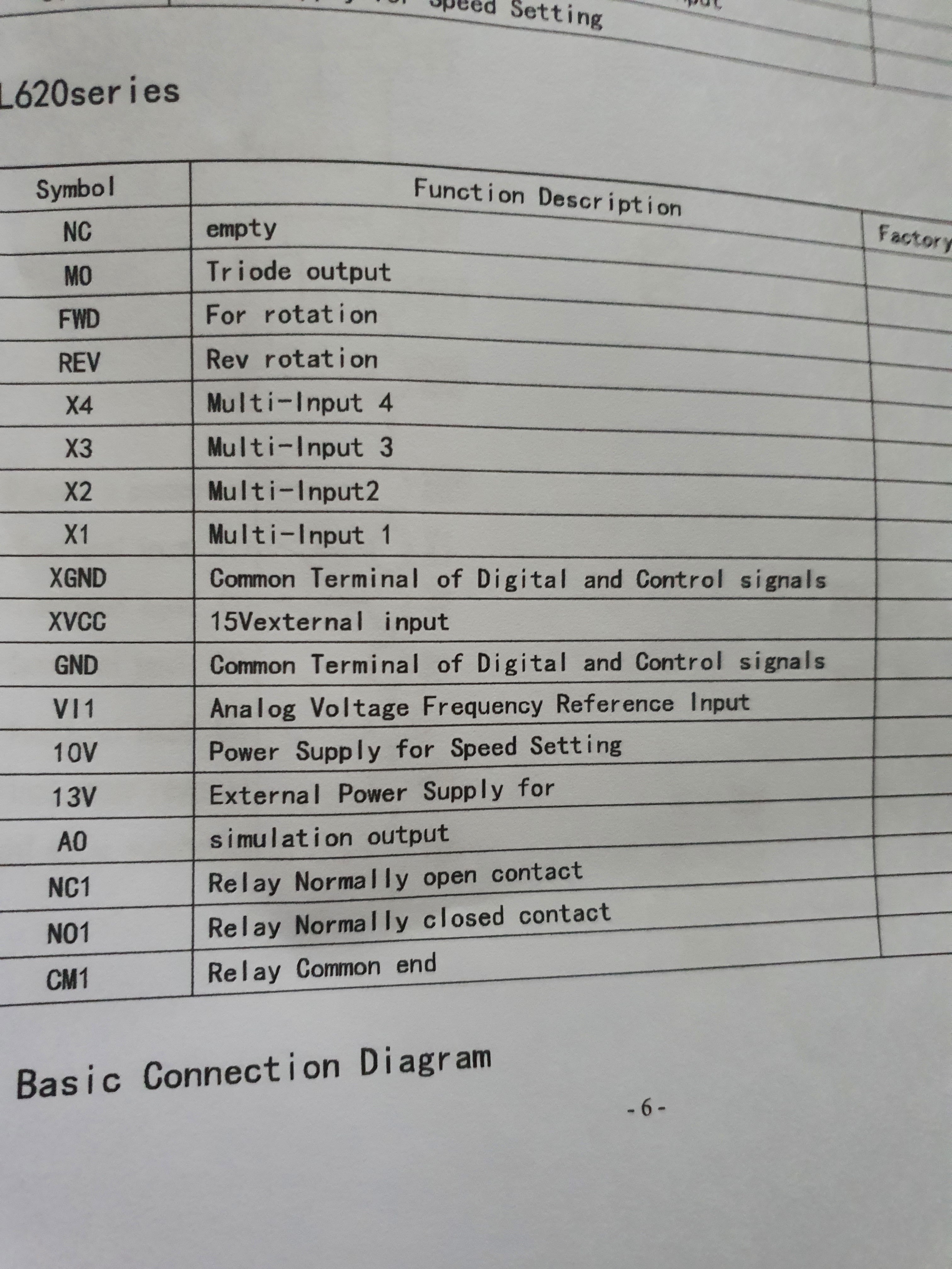
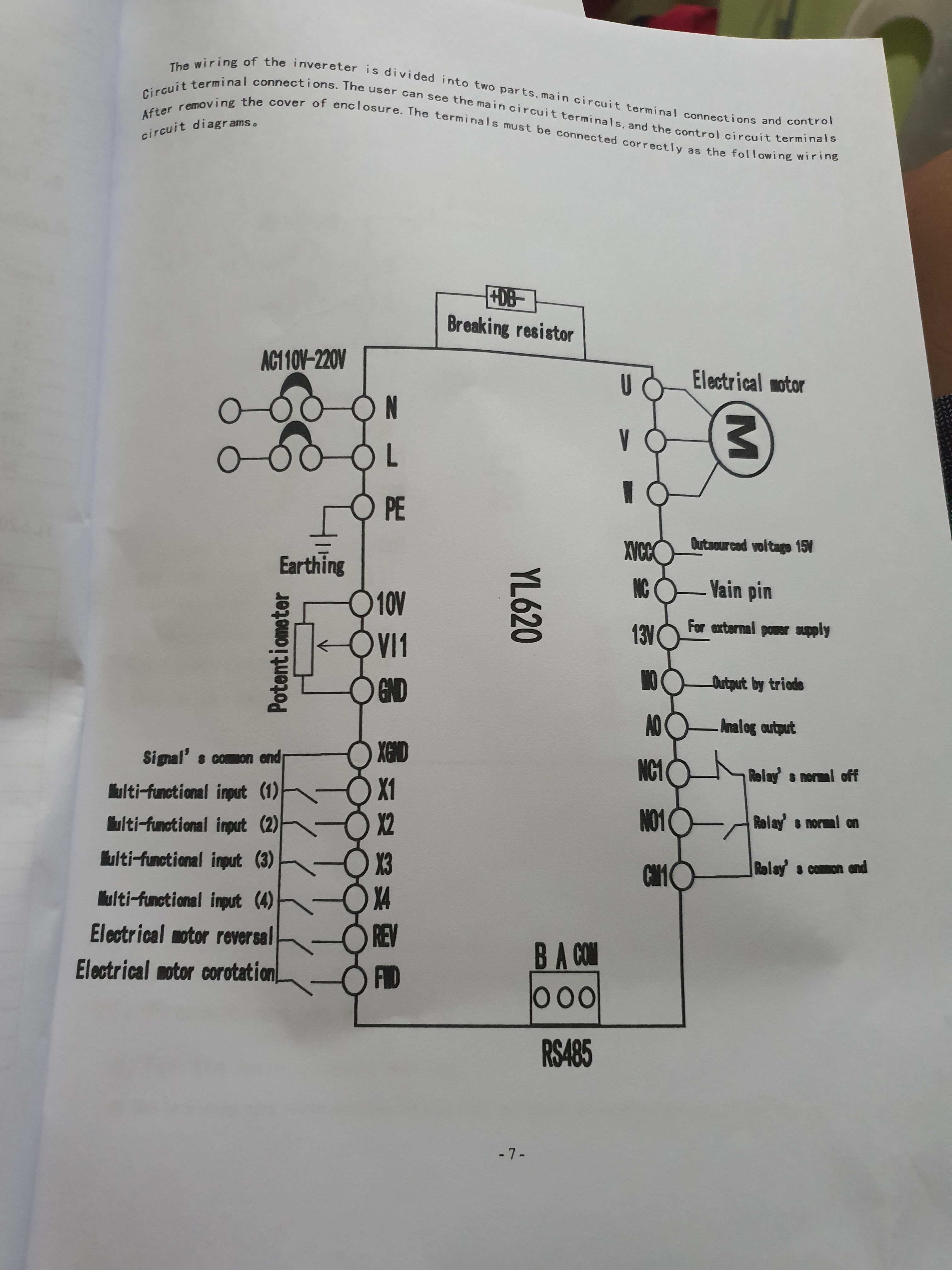
I have no special knowledge of VFDs, but I searched around a bit. If you go to this product page, you will find a wiring diagram for a VFD that has the same labeled connections as in your picture. As for setting the speed from your control board, I’ve seen a couple of posts on the subject on this forum. The problem is that the output from your CNC control board will be either a 3.3V/5V PWM signal or a 12V/24V PWM signal, and your VFD is expecting 0V to 10V on the connection labeled VI1 (the connection used by the potentiometer in the image). I write 12V/24V because the usual place to get the higher voltage PWM signal will be a fan pin, and the fans on most boards run on the same voltage as the motors.
Here is an area in one topic that outlines a circuit to make the translation with some discussion. At a quick glance, it looks like the circuit is using a 12V output from a fan pin to drive the VFD.
I have to agree with gareth that there is likely a number of settings that you may need or will just find useful that you are only going to find/understand with some sort of manual.
Edit: I looked around a bit more. In addition to a DIY circuit, this module is referenced for converting a 5V PWM signal to a 0V to 10V output. You need to feed it 12V (perhaps from your control board power supply), and you will need to tie the ground connection of the control board and the VFD together. A search for " PWM to Voltage Converter Module" will find this module from a variety of sources at different price points.
1 Like
Thats a good start and will get it up and running without connecting it to rambo but with some basic controls. The full manual will give you the details for programming things like soft start/stop, min and max speed and assigning what the inputs and relay outputs do, plus a whole load of options you’ll probably never need 
If it was mine I’d probably look at setting the min/max speeds first and using one of the inputs as an interlock to stop the spindle from starting unless you’re well clear of the cutter.
There is a channel on YouTube called Clough42 and he’s done some good videos on wiring up, programming his VFD and reducing electrical noise, well worth a watch if you have some time to spare.
2 Likes
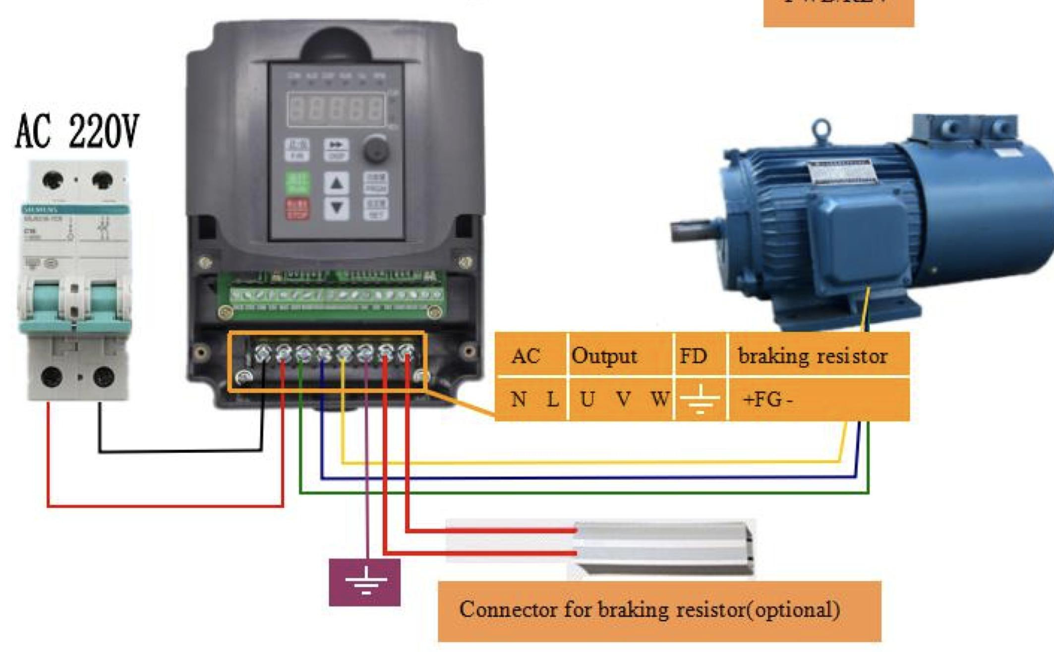
in this picture, seems no need to connect to rambo board if i want to use it now without complicated connections? i can just turn the knob to my desired rpm?
whats that braking resistor for?
do i really need that breaker on the left or i can just wired it and plug?
1 Like
Braking resistors let the spindle stop faster. When you turn the power off they become generators until they stop spinning. The braking resistor puts a load on the generator and makes it stop faster.
1 Like
And like other braking systems, they then have to dissipate the heat from stopping the kinetic energy of the spindle. Mechanical breaks use friction, braking resisters use electronics, but the energy has to go somewhere. They get HOT.
2 Likes