Here is my suggestion:
Widen the space between the rails to allow the X stepper to be moved just behind the router, vertically.
Add pulleys to route the belt around both sides of the router so that the belt exits the plate on both sides CENTERED between the rails, thus avoiding any binding and horizontal flexing during deeper cuts along the gantry.
It’s on my to do list, but it would be nice if it was already standard…
Correct. What I’m suggesting that it might be easier for you to reinforce the mounting plate’s connection on the x-rails, each truck has 5 points of contact extended along the rail. I bring it up as an option for you because as I’m sure you realize if you widen the distance between the x rails you’ll also have to redesign everything else.
(I’m addressing maybe helping to fix your twisting problem in your current machine that you mentioned. I’m not arguing against your suggestion for the new design)
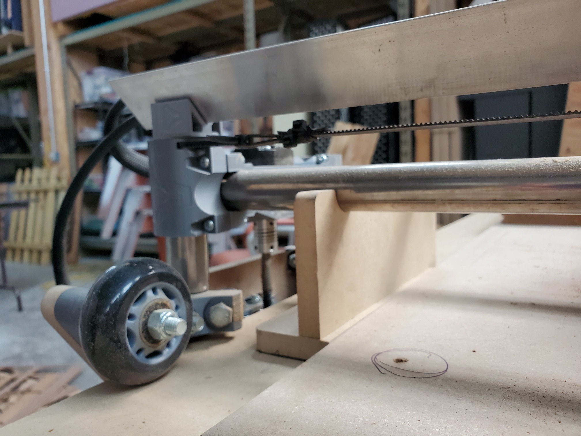
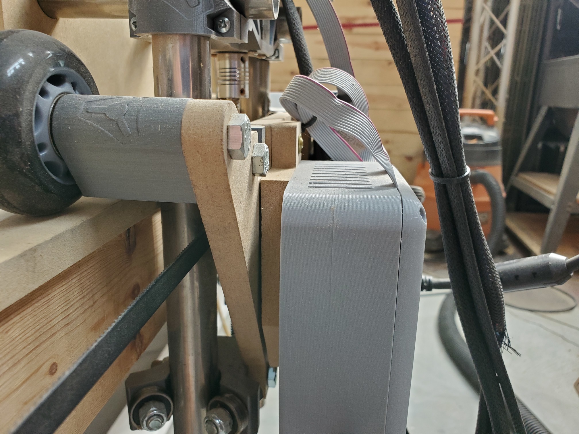
The only critical thing I have added to my Lowrider is the x-axis cable management.
It was a bit of a hack job and I’m sure Ryan could design something nicer.
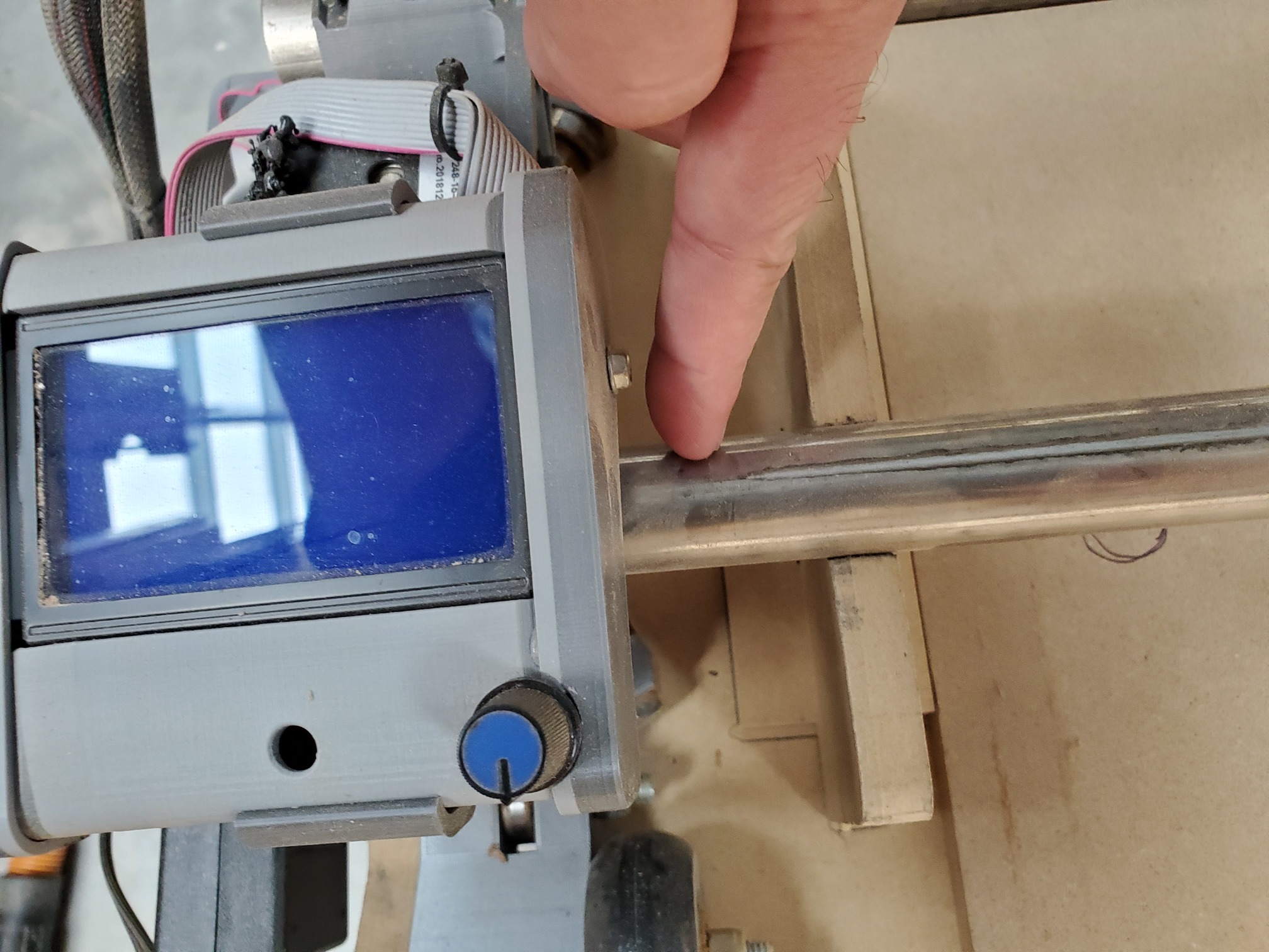
I plan to add some end stop pipe clamps from the Primo part list to easily zero my x-axis up against hard stops when setting the origin. You could include the same part in the printed files for the lowrider. Finger pointing to where I would add them.
Some stand park assist feature. Maybe a kickstand that flips down on each side so it can easily be parked? Or a cradle at the end of the Y axis where it parks itself afterwards. I have a xyz position in my EstlCAM post processor that moves that gantry when a job is done. Then I hit the e-stops and it lowrides down into the cradle. Then I have a ritual after I power it up to get the z level on both sides before I engage the steppers. Some sort of auto leveling on Z would be awesome!
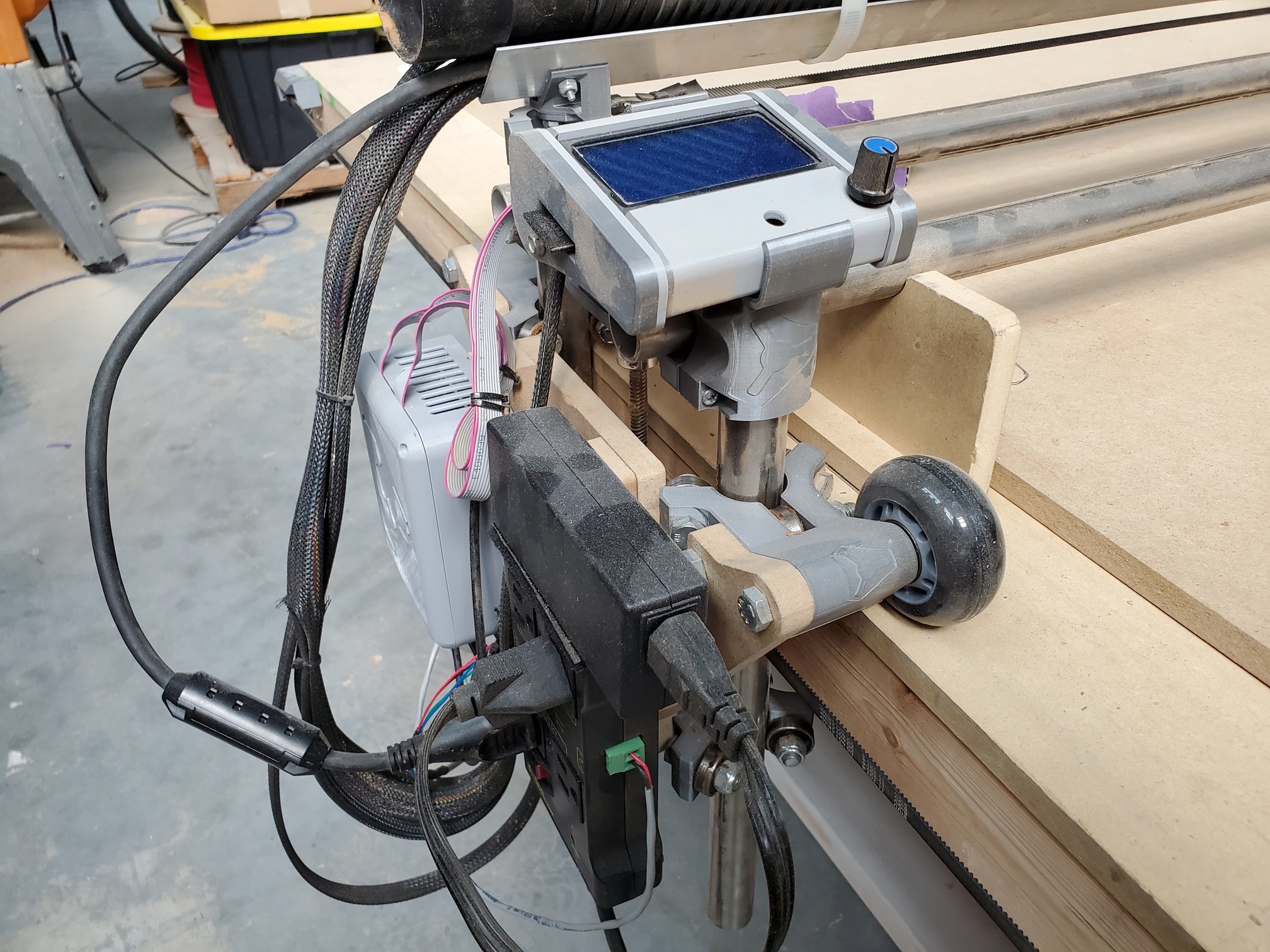
A modified Y plate to accommodate all the junk we want to hang off it. Maybe a double plate with standoff holes to clear the z axis stepper. I cut an additional Y plate to use as a standoff.
I think I’ve noted this to you before, @vicious1, but maybe this is a good thread to put it on record. The hole spacing for the 611 mount was off in the dxf. Off the top of my head the actual 611 base’s holes are spaced 61mm but the dxf has them at 60…? It was a minor difference and minor issue but enough that I had to embiggen my holes with a drill. So maybe diagonal elongated holes would be a nice feature here to also allow for forgiveness in fabrication?
Also to that end maybe a more universal mount hole pattern. I have no idea what other router base’s hole pattern’s are so maybe it’s a moot point.
@ByronM Mayeb you want to update the first post with a solid list as it comes in and hopefully refine it. Of course, no promises, but if it is nice an organized I would be a major punk to not to give it all serious consideration.
I am following along, but running in circles with Primo stuff still. So I might not be replying but I am reading.
How often do people change tools? In my case I’ll be switching back and forth from a router to a plasma torch, and maybe an air scribe some day. It would be nice to have a quick change system. Maybe something like where the main mounting plate accepts a separate universal/generic tool mounting plate that is quickly attached or removed with something like toggle latches? The user could fit what ever tools they needed to the generic plates.
Sooooo… I know the idea of a vertical mounted low rider has been discussed many times. I know there are several flaws with the idea. But… what if we designed a new Machine. Hear me out before you start to hate on me.
The two main reasons you would want a vertical machine is because it would save a TON of space while in use (and when stored) and you can easily reach the entire work piece while it is being worked. ( unless it is too tall for you) the other minor advantage you would get is chips will fall down where they will be less spread out.
How could we get past some of the design flaws of using a low rider set vertical? Lighten the load as much as possible. Remove the LCD controller and the motors. Change to a core XY system so the motors are not part of the moving assembly. The problem with a core XY with long belts is they tend to sag and walk off the pulleys. Well in this case that shouldn’t matter because they would be mounted vertically so they would sag in alignment with the pulleys. With the core XY you not only remove weight from the motors but you make it so there are two motors (possibly even 4) holding up the weight of the working assembly and tool. Anyway it should work. We would probably have to use NEMA 23s instead though.
This design would be better than the Maslow CNC (I don’t think I spelled that right) because it would remain accurate in the corners and it could be used to work a full sheet piece.
Anyway it’s a thought I have been bouncing around. Feel free to give honest and brutal feedback.
I will delete this post and move it to its own thread if asked.
No objections here, no idea how that would pan out though. My first thought is I wouldn’t want to design it myself as I don’t like hitting myself in the head with a router.
Would definitely need a good clamping system for smaller bits and heavier bits may be troublesome with just holding it up and misalignment. I think vertical makes gravity work against you more than it helps. It depends on your projects of course, if all you do is full sheet engraved signs, makes sense. You could probably do something at a 45 degree angle to halve the width and go 90 when storing, would need the wheels on the bottom again though probably.
I think it’s definitely worth considering. I would stay away from corexy, because it is just too much belt and when you’ve got a router, a little motor won’t kill you. You could put the “lifting” motor on the top and not o. The plate if you were really concerned.
Here’s what my dream feature list would be:
Rails made from tubing. We know tubing. The wheels are great for mondo LRs, but if you have to deal with gravity pushing to the side, we will have more requirements for the rails, so just make them huge EMT or 1" DOM.
A slight angle. Something like 1’:5’ so the base is about 1’ out and the height stays about 5’ up. This would help share the load between the X and the Z. It will also keep the Z down.
Moar motors. 6 motors should be able to give you more strength on the vertical X axis. You can have a belt loop with one on top and one on bottom, or them both on the plate.
Dust collection, laser, pen included.
None of this super thick stuff. Just keep it to 3" and it will forever be a panel cutting machine.
There would be a ton of issues still. It isn’t trivial to lift a 15lb gantry, especially with a belt. There needs to be clearance underneath the bottom for the Z axis, but still be sturdy enough to stand on (because people trip). Then there’s all the details of getting everything aligned, but adjustable enough for someone to build the table with a circular saw and a straight edge.
I have a lot of experience with the Maslow CNC and the assessment about accuracy issues in the corners is pretty… accurate. There was discussion about using stepper motors and belts instead of DC motors and chains, but the price of the stepper needed to support the weight of the sled as well as needing some sort of worm-drive gear box (so when power fails it doesn’t plummet to the floor) was pretty much a deciding factor against it… no one worked on it. The nice thing with the lowrider is that if power fails it just stops moving.
I had a prototype of a four-motor, self-contained Maslow working at one point, but ran out of steam troubleshooting why I couldn’t get clean movement. I thought it was the PID values and spent many nights trying to work them out only later to discover, when I repurposed my motors to build my robot, one of the encoders on a motor become loose off the axle and that’s why I couldn’t get clean movement. Nevertheless, I know a four-motor design is being worked on by the Maslow creator and I expect it will work much better than the current Maslow.
Also, keep in mind during any thoughts is that no matter how good dust collection is, some will drop… and if there’s a bottom rail, belt, something, it will get covered.
I personally I’d like to see a 5-axis MPCNC rather than a vertical MPCNC…
I think vertical or nearly vertical is very reasonable. I think a counterweight could mitigate the constant sideways (downward) load on the X axis so that a single Nema17 might still be enough, but doubling up with two Nema17 would make it a non-issue.
The one thing might need some thought is how to hold the gantry “down” in the Z direction. A tilt would help but I’m not sure how much tilt would be needed to have confidence that the Z won’t pop up by itself. Too much tilt and it defeats the space-saving.
And there’s no reason not to also have a 5-axis MPCNC. It’s not one or the other.
15 degree tilt seems to be sweat spot for maslow. It was part of the problem with how much space it took up. Some have made a wall mount that you can swing out to tilt it when you want to do cutting.