Is there a example of where the best place to mount the end stop switches on the Low Rider 2?
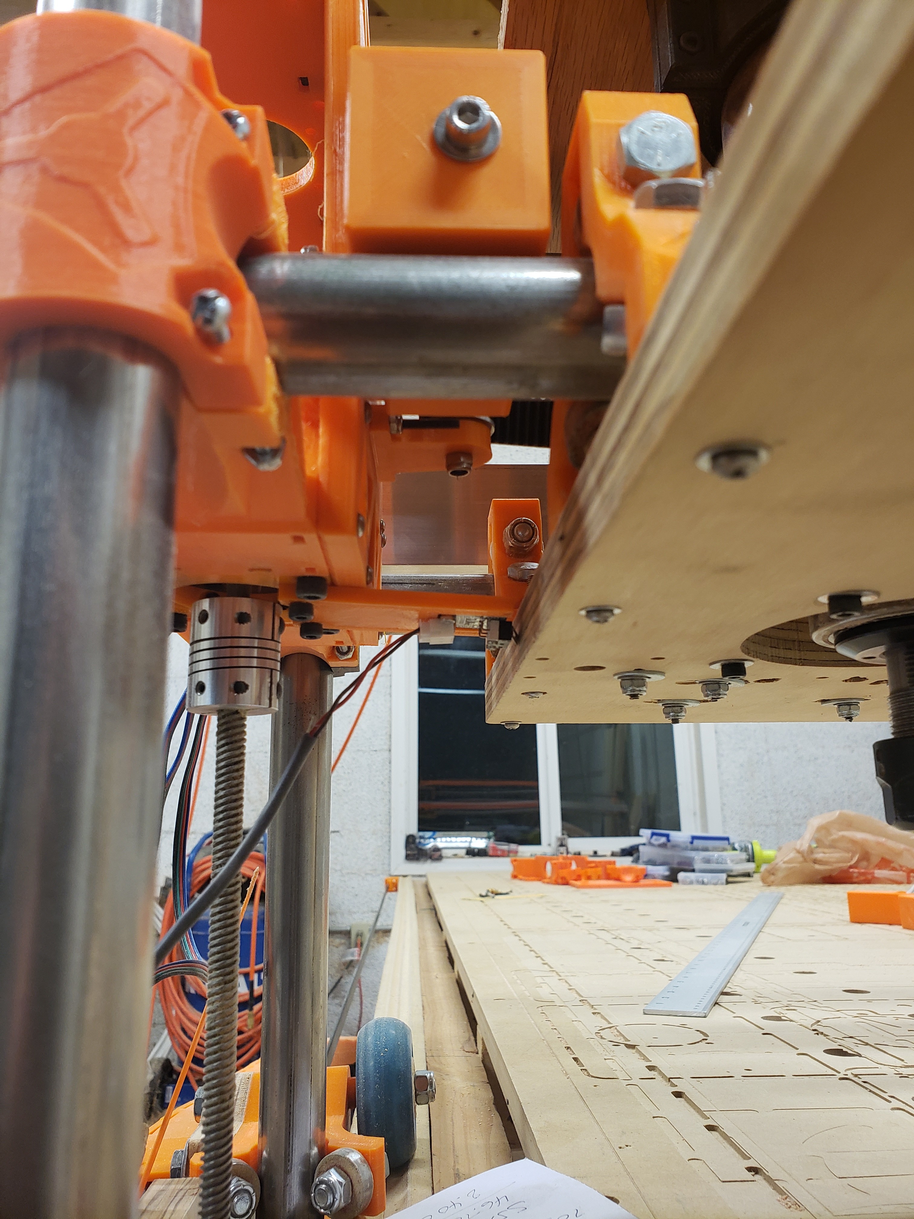
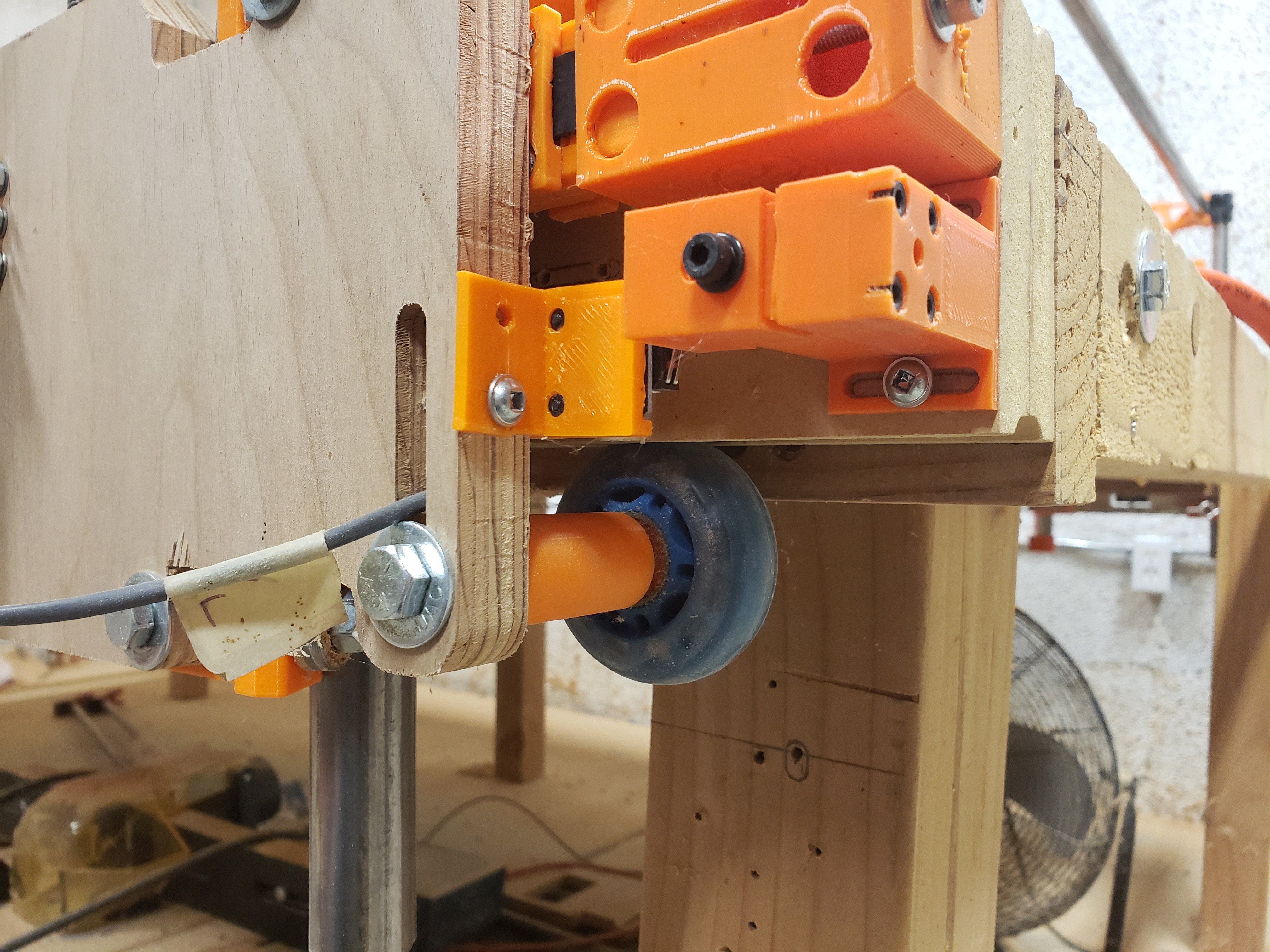
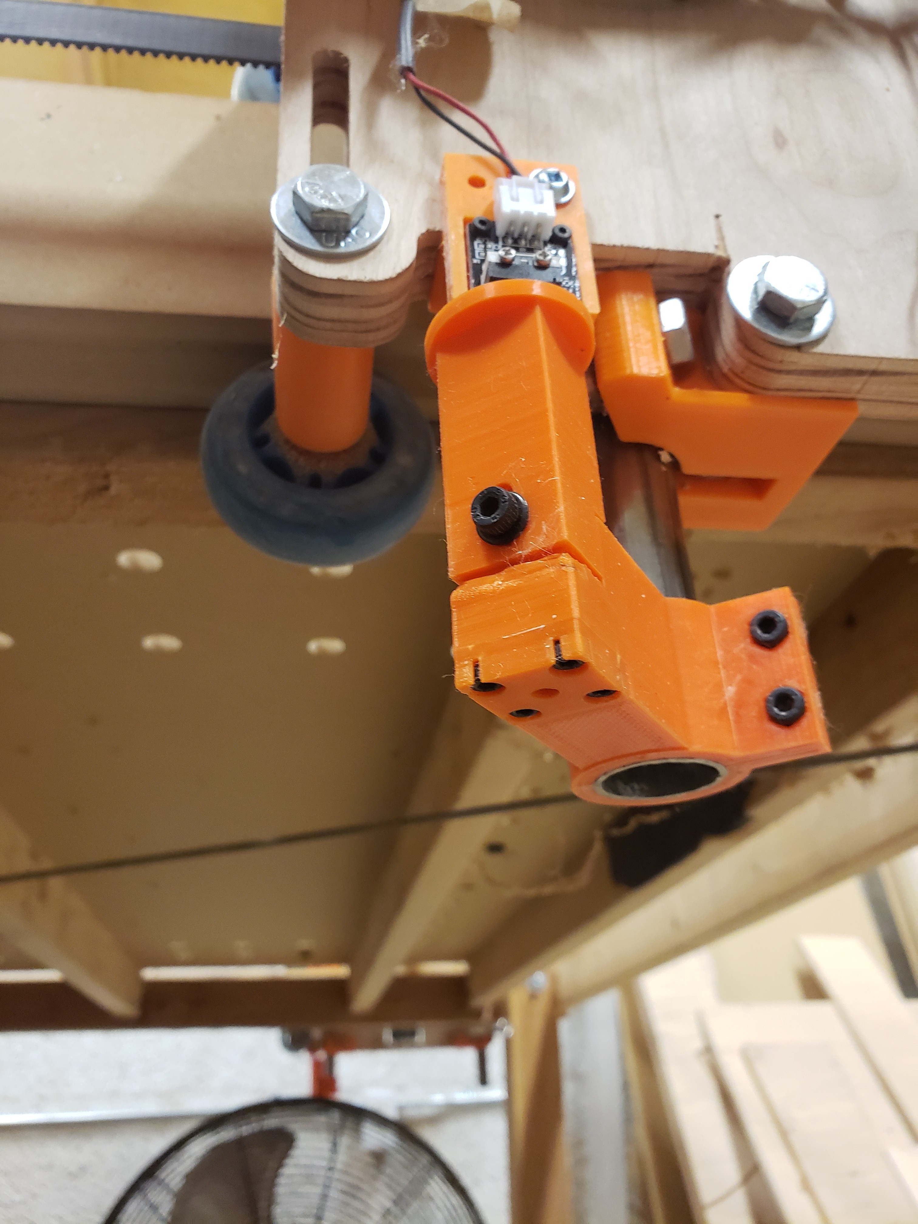
Here is how I set up my end stops:
For the X-axis I made a plate for the reprap switch (same as on my Ender 3) and attached it to the XZ_MAIN closest to X=0.
For the Y-axis I designed a switch mount to attach to the Y-plate. I designed a base to attach to the table closest to Y=0. I designed a slide for the base. I use M4 socket cap screws and Ender 3 bed springs to drive the slide. I designed a cap to lock the M4 in place using 4 M3 screws. This assembly allows fine adjustments for squaring the gantry.
For the Z-axis I designed an assembly similar to the one for the Y-axis that is attached to one of the Z pipes. This assembly allows fine adjustments for leveling (or making the spoilboard parallel to) the gantry.
BTW - there are also M4x6mm screws to lock the slides after adjustments
2 Likes
The dual LR was added because I kept answering the questions in the forums. But it was after the LR 2 design and I don’t think Ryan has made much thought on the mechanical solution. So any parts that you find will be from the community.
There used to be an endstop clamp that fit a pipe (from Ryan) that would work for at least the Z and X.
I am looking to just add z stops and not x and y (I’m fine with pulling the gandty into the hard stops for x and y). I currently have a mini rambo with the z steppers wired together to one connector.
Is it possible to rewire the z steppers independently but keep the y steppers together and then only home upwards for the two z steppers? I need to find a more accurate solution for consisten Z height across X.
Thanks everyone!
Dan
Yes. How much work are you willing to do for it?
It is essentially the duallr code for the rambo (from marlinbuilder releases), but with the dual Y turned off and the board changed to mini rambo.
It even has G38 enabled so you can use G28 to auto square up and then G38.2 to prob the top of the work surface by probing down.
And it would be okay to just rewire the z-steppers individually and leave the other ones as is?
I’m not going to run into a situation where I can’t go negative on my x and y because I’m homing z or something like that?
Am I correct and assuming I would plug each z into the two z connectors on the mini or would I use the extruder connection for the second z plug?
Thanks as always Jeff, it seems like you never get tired of helping!
Tom, would you be willing to share your STLs?
Yep.
That’s called “soft stops”. You can disable them in the config, or with M121 (or M112or something, I can’t remember). But I think they will only have an affect when you home X or Y.
The E0 plug would be for the second Z, amd associated with the Xmax endstop. The first Z would use Zmax endstop. The probe pin is Zmin.
The second Z connector is just wired in parallel with the first. Don’t use it for cnc.
1 Like
Dan,
All of STLs for my Lowrider build are available on my Google Drive:
1 Like
Thank you Tom for the information and the STL files
i dont know where is the best place… but i create my own (for y and z)
perhaps this can help…