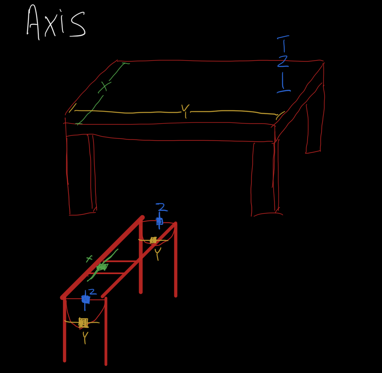
As I’ve been going through the instructions for the lowrider2 I have been taking notes but am getting confused. I could be wrong, but it seems that the different axis (x,y,z) are being mixed up though out the documentation which is making it difficult for me to figure out which is supposed to be which. Is the drawing I made below correct?
For the Primo, the Y axis is the lower rails, and the X axis is the upper. Z is always perpendicular to the table.
For the LowRider, Y is the direction that the wheels roll along the edge, and X is the rails across.
In general, Y is usually the longest axis by convention.
Not sure where the documentation is mixing them up, I thought that it was very clear.
What you’re maybe getting mixed up on is that the X gantry rail gets bolted to the Y trucks, and the Y gantry rail gets bolted to the X trucks on the Primo. This is because the trucks move in the specified direction along the outer rails, so they are named for the direction in which they move. When the X trucks move, the core moves in the X direction, along with the Y gantry rail. When this happens, the core isn’t moving along the Y gantry, it is moving along the X gantry (Bolted to the Y trucks) which is not moving.
Sorry, probably not making it clearer, but when it’s all assembled and you watch it move, it makes sense.
Your drawing is correct, but it is also possible to swap the X and Y axes.
It is important to understand the “right hand rule” when arranging your axes, configuring their directions of travel, and deciding on the machine’s origin point (X=0, Y=0, Z=0). When facing the table, X positive should move the tool to the right, Y positive should move it away from you, and Z positive should move it up, away from the table.
On your drawing this would mean you’d be facing the short edge of the table standing at the left of the drawing. The machine origin would be to your left with the tool closest to you and the tool at its lowest.
If you swap the X and Y axis, you’d be facing the long side of the table standing at the front of the drawing. Again the origin would be left edge closest to you with the tool all the way down.
Hi, thanks for the reply. From what you are describing it looks like my drawing is correct. The part of the manual that confuses me is the part talking about dual endstops. I wanted to do dual endstops but couldn’t make sense of the instructions. Its probably better that I start of with the non dual endstop firmware for now anyways. Thanks for your help
Hi, thanks for the reply. Your explanation was very helpful. The documentation regarding dual endstops is still a bit confusing to me but I will have to re-read it with the information you have provided in mind.
I just couldn’t tell with the Primo drawing if the Y rails were higher or lower.
Each Primo truck mounts a motor and an endstop switch. So long as those agree with each other, the dual endstop firmware will work fine. It’s not actually terribly complicated.
The trick with dual endstops is that there will be a switch at minimum travel of both rails, 2 for X and 2 for Y. The switch has to match the motor. Then, during homing the machine can adjust the squareness of the machine.
It is safe to use the dual endstop firmware from the start and just not add the switches or configure the offsets until you’re ready. Just don’t try to use a homing command - homing relies on those end stop switches to find the origin. Instead, you’ll manually move the machine to where you want 0,0,0 to be and tell it that’s where it is with a G92 X0 Y0 Z0 command.