Hey, not sure if this is the right place to post this, but why not dual conduit rails for the Y axis on an LR3 CNC?
Wouldn’t that make traming and squaring it much easier and more consistent?
Hey, not sure if this is the right place to post this, but why not dual conduit rails for the Y axis on an LR3 CNC?
Wouldn’t that make traming and squaring it much easier and more consistent?
Hello @Speed0verdose, was curious about this too. Already seen LowRider 3 CNC, LR3 Release notes - #6 by vicious1 ? Are you asking about a Y axis rail on the left (X min) and right (X max) side, or, are you thinking about two conduits on the right (X max) side?
Ah, thank you. I did not see that.
I may try to modify my LR3 for the Y axis to utilize a 10 series extrusion and linear bearing pads from 80/20.
I’m modeling my build based on Mcunn’s portable/modular LR CNC and the extrusion wouldn’t be too difficult to incorporate into the rails (i don’t believe)
I was asking about using a rail on both the Xmax and Xmin for the y-axis. I understand over-constraining and being precise, but I actually welcome the challenge.
I also have one of these that I was trying to figure out if I could incorporate into the LR3 on the Xmin Y axis that I could use for both tracking and squaring up my work pieces.
+1 for Mcunn’s portable LR bench, have/am stealing some of his ideas for my build ![]()
It’s interesting to see the different Mods people are exploring and having fun with. Already seen @claytonisbob’s conduit everywhere LR3 Build 3 Tube Gantry LR3 Build: An Idiots Tale ? Triple conduit gantry, double conduit rails for Y-axis. Even has conduit inside conduit, to explore stiffening his build.
Look forward to seeing your build journey!
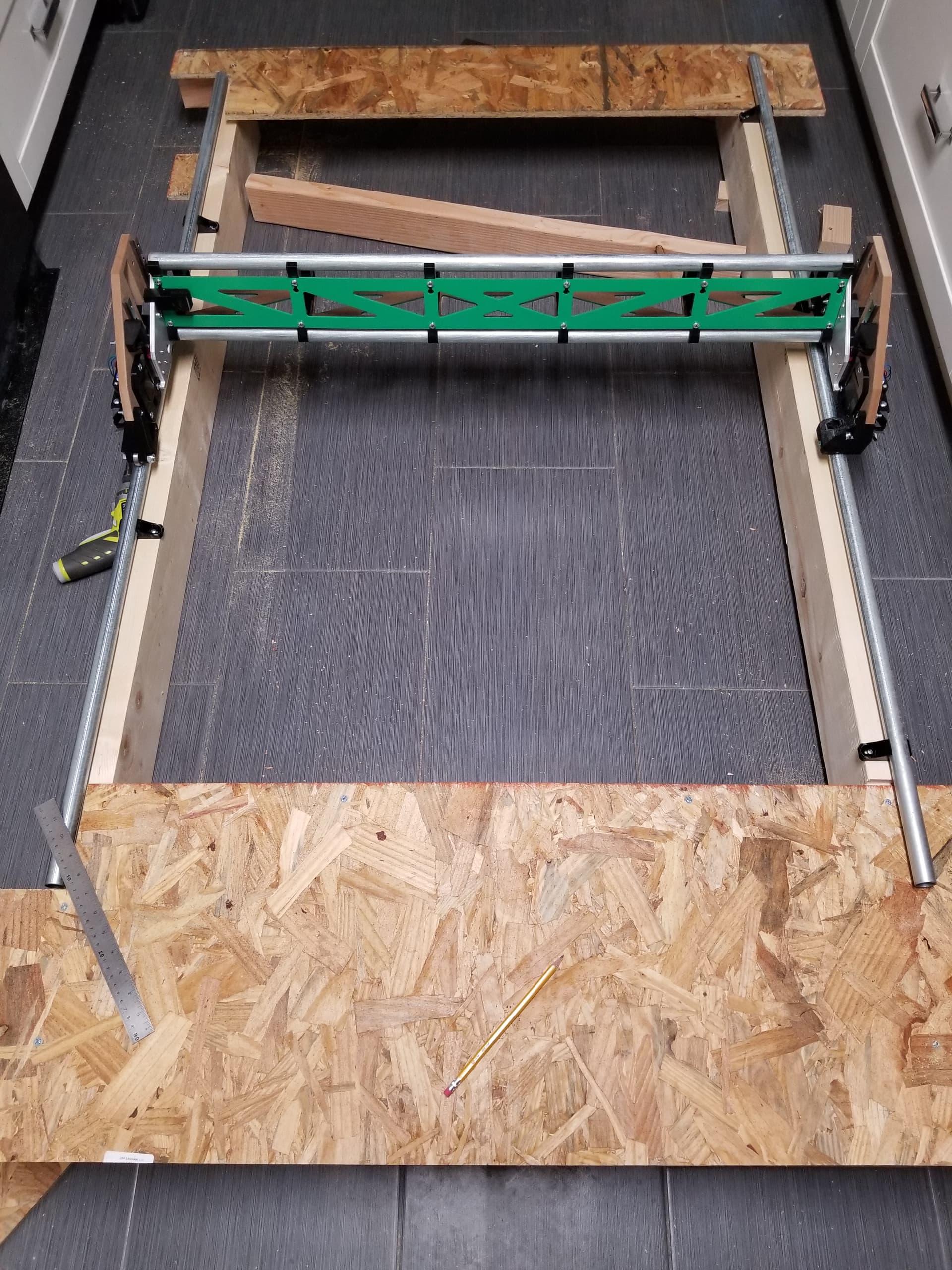
I’m building one with two rails
The left one is flush with the table top and the rollers are flat, same as if it were rolling on table top. Alignment/spacing has to be just right.
Curious why using wheel bearings instead of rail rollers on rail? Considered ply box or box metal if concerned about wood not being flat enough? Or are you using curved rail to have self chip clearing rail? Other reason (s)?
Wheel bearings is because of the overconstraint problem. They are 7 mm wide and my thought was I should be able to get accurate enough not to fall off, but even then it’s not quite as simple as I anticipated. The rail is cheap and the mounts are already designed. (Provided I design the table around them that is.)
Square steel tube would also work and it would provide a larger surface, but I need 5 feet so its a special order. I prefer a continuous piece so there is no issue of discontinuity at the joint. With square tube it’s not obvious how to mount it. Better might be steel angle and I could drill holes in the side.
The YZ plate is almost, but not quite parallel to the rail, I’m assuming because the beam is not perfectly square to the XZ plate. The wheels don’t both track exactly in the middle of the rail. I think it will work fine but I will probably shim the XZ to beam connection so the rollers are both centered.
even with the issue of perfect alignment, couldn’t you mirror the Front & Rear rail rollers and attach them to the plates?
Yes, you could use the same rollers (mirrored) on the YZ plate on the left (x min) side. Then you could also mount the rail on top of the table instead of having to inset into the table like I did.
Getting the spacing perfect is the only real issue. A small error can have a surprisingly large effect. If the two ends are fighting each other (even from a small 0.1 mm error) then it could behave as if you had play in the system.
To put it another way, if you have error in the distance between the tubes:
The error in the rails can somewhat be compensated for (by referencing one edge), but the Z is harder to remove.
It just occurred to me, one rail could be allowed to float in X. Since it’s round, you could just lay it on the table and it can adjust itself to sit under the YZ rollers. Maybe add some blocks to the table to constrain it so the far end doesn’t roll away.
Ideally you would prop it up so it’s the same height as the right side (positive X) but you might just use the dual Z homing to correct that few mm of height difference.
I probably would have done that if I had thought of it sooner.
That’s clever and all, but converting the downward pressure into a roll for the conduit might require a lot of weight. The conduit would definitely have to roll smoothly. I think the force to roll the conduit is proportional to the amount or error too? So it may have some band of error to overcome the stiction.
“It’s interesting to see the different Mods people are exploring and having fun with. Already seen @claytonisbob’s conduit everywhere LR3 Build 3 Tube Gantry LR3 Build: An Idiots Tale ? Triple conduit gantry, double conduit rails for Y-axis. Even has conduit inside conduit , to explore stiffening his build.”
I like conduit 
But yeah, for the second Y rail I just flipped the roller assemblies in my slicer, worked great.