Wiring diagram for skr board

Hi there,

I’ve got my wiring almost tidy, wondering if there is a schematic or image reference for the skr for the steppers and end stops based on the dual lr firmware.

Also, anyone have a link to some longer cables for the skr tft screen? The ones that come with it are too short to wire it into the top and then into the board.

1 Like

Okay I need to get on that ASAP.

I do believe there is most of it shown on the SKR page. There are also some pictures on printables for the cases.

1 Like

doesn’t need to be a full schematic, but something to show which stepper is preprogrammed to which driver port as well as which pin input is to which endstop. I’ve looked on printables and the other pages, but can’t get a clear view of the driver /stepper matching. i can make out some of the labels but not all.

the SKR page certainly helps a lot. Glad I saw the note regarding the sensorless pin being bent. Does the board complain if the pin is inserted even though the firmware isn’t using sensorless homing?

However, in the section regarding dualLR endstops, does the preloaded firmware ship in extruder=0 or extruder=1 mode? skr extruder wiring

also regarding endstop pins, the diagram/image, looks to be for MPCNC as it doesn’t show 2 z stops. are the 2 zs replacing the x stops and the blank input used for the x or something different? endstop wiring

last questions regarding the power, both the motor power and main board power are connecting to the same PSU correct? PSU looks to be more than adequate. I was thinking to simplify wiring, just jumpering the motor power to the main board port and main board wiring to the PSU, or have you ran each cable out and both into a barrel plug to connect to the PSU plug? just looking for some recommendations from those that have built these before and may have more knowledge of the SKR’s tolerances for power draw.

i’m considering just switching the board connectors to JST, vs removing the JST seats on the board to ensure a snug fit, since I’ve had to cut the wires anyway to keep cable routing/size acceptable (my build is only going to be roughly 30x70 vs a 48x96 build so have lots of extra cable). either way crimping either is a PITA (i’ve learned over time, seems to be easiest to get a good connection by first placing wire in, hold, use a needle nose to pinch the cable support part onto the wire sheathing just a tad to hold it together, then insert into the middle crimper section, crimp the support part down, then slide the connector back out a little (so crimped support part is visible, and crimp again over the exposed wire crimp point in the same middle crimp port). Other videos show crimping then going down a size and crimping again, but that just tends to crush your connection and will cause for cursing when you can’t properly seat it in the black sheath)

couple images of where i’m at
front angled view


Thx to my wife for allowing me to assemble on her pretty table, since my table that this will be mounted to (my table saw table) when operating is permanently outside under cover, so, i’ll be storing this in my enclosed trailer workshop when not in use and just bring out to set up and calibrate before doing a job-o

1 Like

YEs

E=0

In that case It shifts. I will get a diagram up ASAP. X1 Y1 touch plate is the same the top row is Z2 Y2 Z1.

yes.

exactly

yup,

Sorry for being so short. I tweaked my back this morning pushing the pallet up bearings up the driveway and I am drying. I am going to take it easy for a bit but will check the emails to see if you need more help until I get the rest of the info up. I have three pages of notes left to get in the instructions.

3 Likes

This should help. I hope that diagram gets into the docs at some point. The skr and rambo have different names for the endstops, so it ends up being a lot of combinations of what to wire where.

6 Likes

Will pray for you!

1 Like

no worries, get some rest!

really appreciate the quick responses. I think i’m good to go for now

much appreciated!

1 Like

Got the wiring all worked out. The diagram helped a ton. End stops triggering proper. Regarding x and y max, can I enter that in the screen so you don’t accidentally try to move more than it’s capable similar to in 3d printer firmware? This weekend going to work on mounting it to my table and begin test moves/cuts now that electrically everything is doing what’s expected.

Also, I didn’t see anywhere in the touchscreen to zero out the xyz. Only home

1 Like

Those are soft stops, and no, they don’t really work well on this machine, because you can’t set the bed size without editing the firmware.

2 Likes

The zero x, y, z buttons are on the home options screen on my V1 default Dual Endstop LowRider firmware.

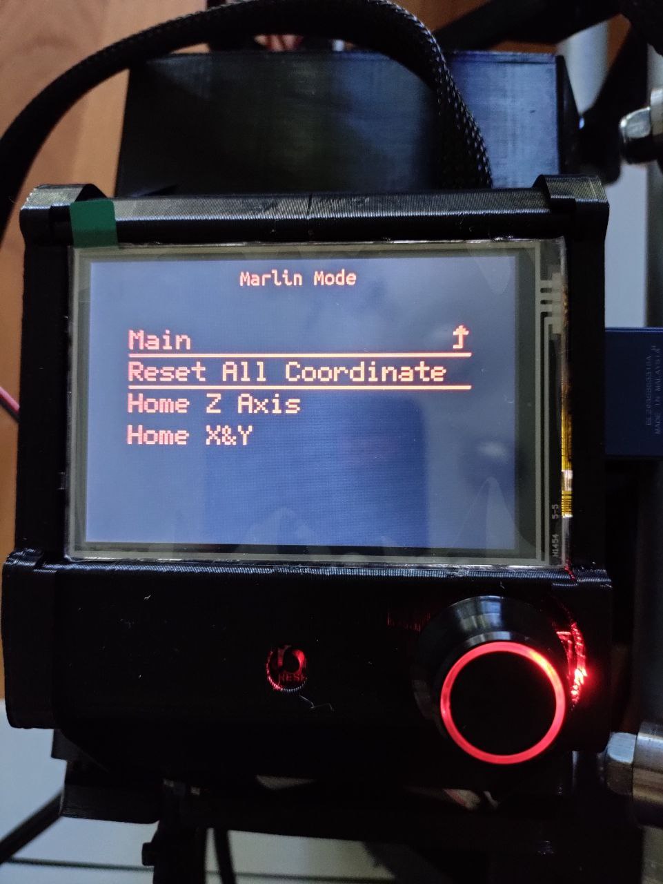
Is that the reset all coordinates option? I don’t see any other options in the preflashed firmware.

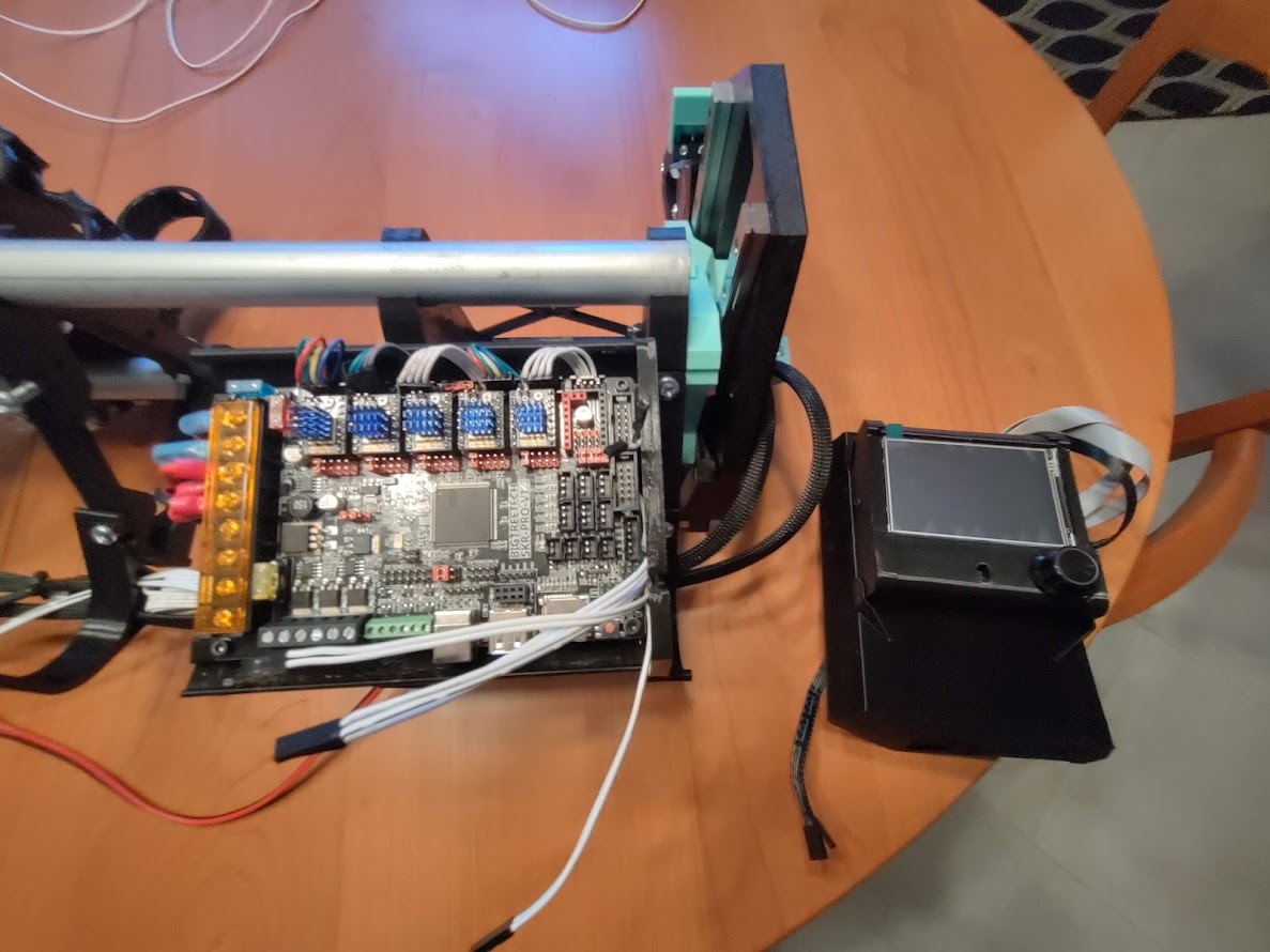
the touch interface, only seems to have a customized “emergency stop” other than that looks like a normal 3d printer touch interface but with V1 color scheme, which i read elsewhere in the forum here that is mainly because the touch customization was too much of a pain. I may look further into customizing the touch firmware, but only well after i have this thing performing well completely stock. I’m comfortable with 3d printer firmware, but the whole CNC is very new to me.

I’m trying to understand how resetting to “0” before a print and how the touchplate probe works.

When I did the crown test, I first did it in the air and noticed that just starting ‘engraving’ immediately after hitting print, with no pause for zeroing things out before it ‘cut’. So when I printed the crown for real, I just manually moved my core (through the interface) to the proper position on my paper notebook, and then when satisfied hit print and it did it’s thing.

just trying to understand how the touchplate probe works and how/what to do in estlcam/touch screen for zeroing things out when I go to do real cuts.

I did load all of the recommended configs for estlcam for pre and post gcode, but don’t really understand how the touchplate matters at all with it. The beginning custom gcode snippet essentially just says at start, where it is right at the time of starting print is all zeroed out, then it homes, and then it starts as soon as I hit resume, there seems to be no prompts for the touch plate to be used at all during this process. Am I missing something?

G91 ; Relative positioning, just in case
G92 X0 Y0 Z0 ; Set Current position to 0, all axes
G00 Z5.0000 F500 ; Raise Z 5mm at 8.3mm/s to clear clamps and screws
G28 X Y Z ; Home in order, w/zprobe
G92 Z0.5 ; Account for probe thickness (set your thickness)
G00 Z5.000 F500 ; Raise Z probe off of surface
M00 ; pause for LCD button press
M03 S<s> ; PID, set spindle speed
G90 ; Absolute positioning, just in case

I also didn’t see anything in the marlin mode or touch mode to do any type of zplate or origin zeroing unless that “reset all coordinates” is what you manually hit after moving the spindle to your origin point.

Many of you probably have this down as you’ve been doing this for a while, but this part eludes me from what I’ve been able to search for here.

Thanks for being patient with me. So far building this thing has been the best kind of therapy and I’m excited to get it cutting, once I understand these core essentials

2 Likes

I was talking about the touchscreen mode, not the Marlin mode.

Hello, I am in the wiring my lr3 and i don’t understand the 4 cables from the power supply on the picture of the skr wiring.
Does from the power supply come + and - to power and motors?
Thanks for your help.
Greetings Christian

As shown on this photo in my post:

There needs to be power for the board itself, as well as power for the motors.

The board’s power is listed here as “Power 12v/24v” and the power for the motors is listed as “Moto Power.”

2 Likes

Thanks for your replay, that means 2x + cable from power supply goes 1x to power and 1x to moto, the same in - cables?

Yes, that is correct.

Thank you, perfect, i wish you a happy new year.
Greetings from Austria

1 Like

Have a blessed new year.

To make it a little easier, you can run 1 set of wires from the power supply to the power terminals, then a couple small jumpers a couple of inches long from there to the motor power terminals right next to it

1 Like