I finally have had some time to start finishing off my lowrider again and have been trying to finalize the wiring.
I have my X working correctly (standalone), but have found an issue with my Z’s wired in series.
One is trying to go up, while the other is down.
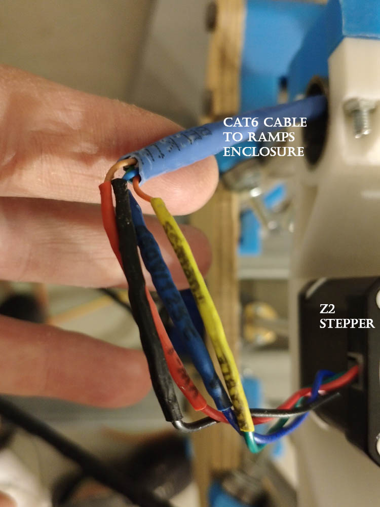
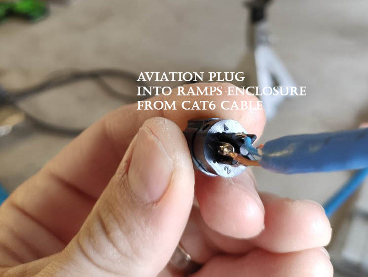
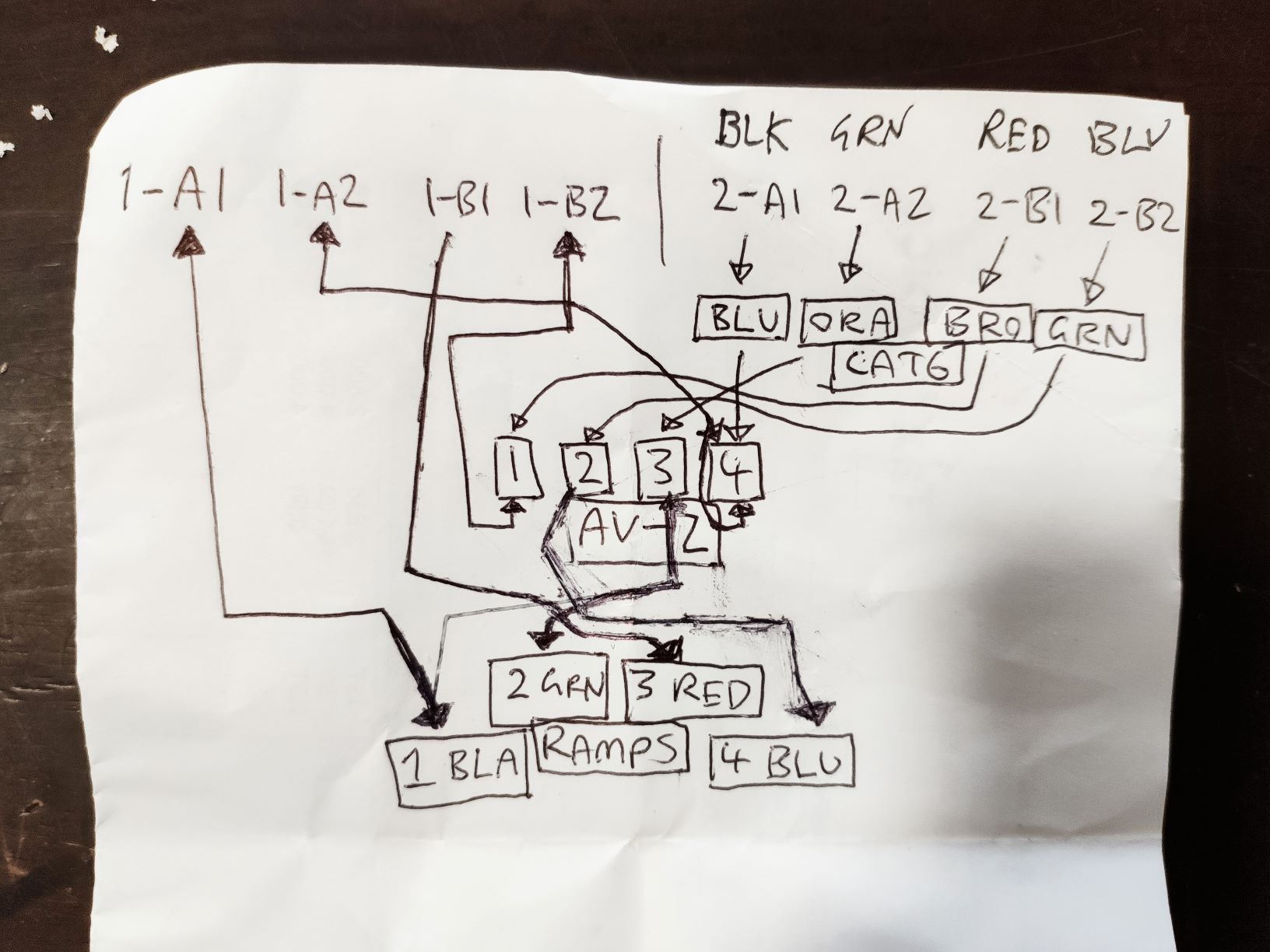
I have seen people with issues similar to this, but I have tried to wrap my head around this only ending up in headache, mainly as the extra element of the cat 6 cable and the aviation connectors complicates things a bit, and my stepper colours are different to the guide (i believe i understand the concept of the dual coils, but need to verify my thinking). I have gone this approach for extra shielding as will be used for plasma at some point as well. (and the wiring is a little nicer / neater (outside the enclosure)).
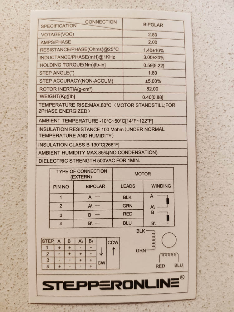
I have just recently found the data sheet on my steppers which i think will help alot and I have done what I can to document what I have currently done.
Where have I gone wrong in the wiring sequence?
Here is a video of them moving in opposite directions (although it is kinda hard to recognize being so far apart): https://youtu.be/0FQoat_g75Q
I have no idea which pins at the stepper are which though.
If you can figure out what to do from that, then go with it. If you are really struggling trying to flip all 4 of them, there is a short cut. You can also flip a motor by reversing one coil. So all you have to do is determine which stepper motor wires are one coil. It looks like you think A1 and A2 are BLU and ORA. So you should be able to swap those two.
You must not have flipped it right. The stepper you have isn’t unique, it will work. I’m not sure what behavior you say when it was worse, but that might be a clue.
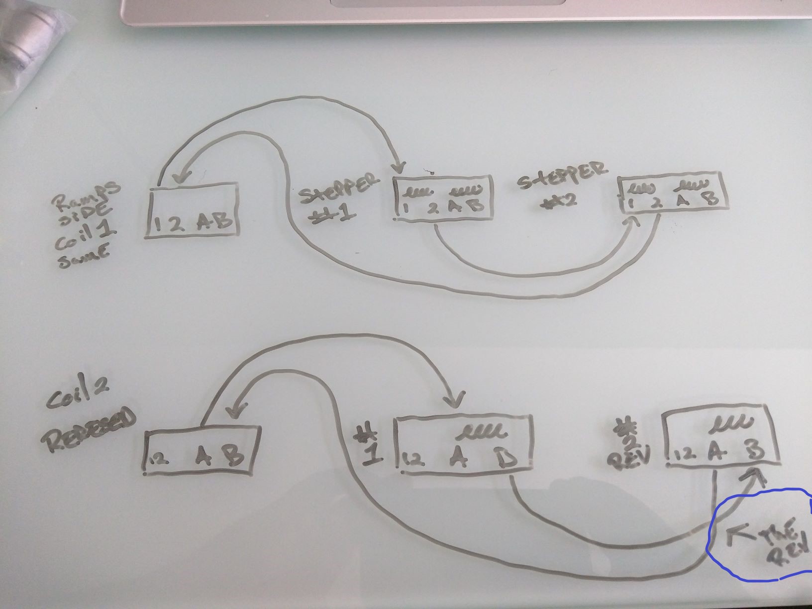
I FINALLY managed to get it working, looking at this post: Stepper motor wiring
Gave me inspiration to work out my wiring on paper, but the wiring on that diagram didn’t work.
Only after reviewing ryans illustration once more, made me see at the end the connections are reversed.
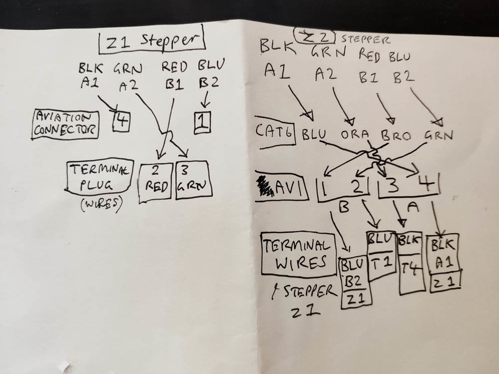
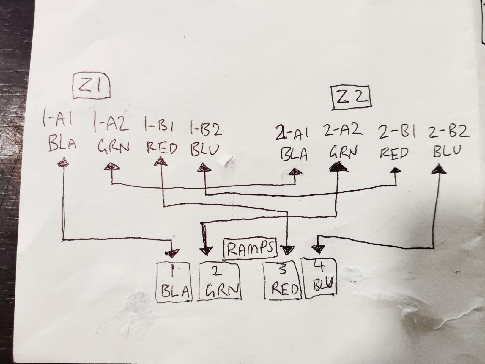
Below are my diagrams that helped me work it out if it helps anyone else.
Time to move onto the next problem. One of the Z Steppers doesn’t align with the rod very well
It has been lying on its side for a couple of months, i wonder if the board or something is bent…
I can see there is a crack in the Y mount / Z rod mount, which makes it more flexible, but i think that is a by-product of something else not being right.
Any ideas?
I had the same issue in my build and concluded it was just the location accuracy of the holes in my Y plate. Just flipping the plate worked perfectly for me.
I second @jeffw’s solution for simply loosening the T8 nut (which feels counter-intuitive, but was in the original assembly instructions). With the T8 nut tight, my z-axis motors were fighting to move , but loosening the nut gave it the degrees of freedom to align itself with the threaded rod and dramatically reduce friction.
Someone on the facebook page ended up point out that my XZ_Main was around the wrong way.
Turning this around resolved the issue.
…However, now i have another random issue where my Z steppers all of a sudden have decided they only want to go down, not up, regardless of which direction i tell them to move in … hmmm…