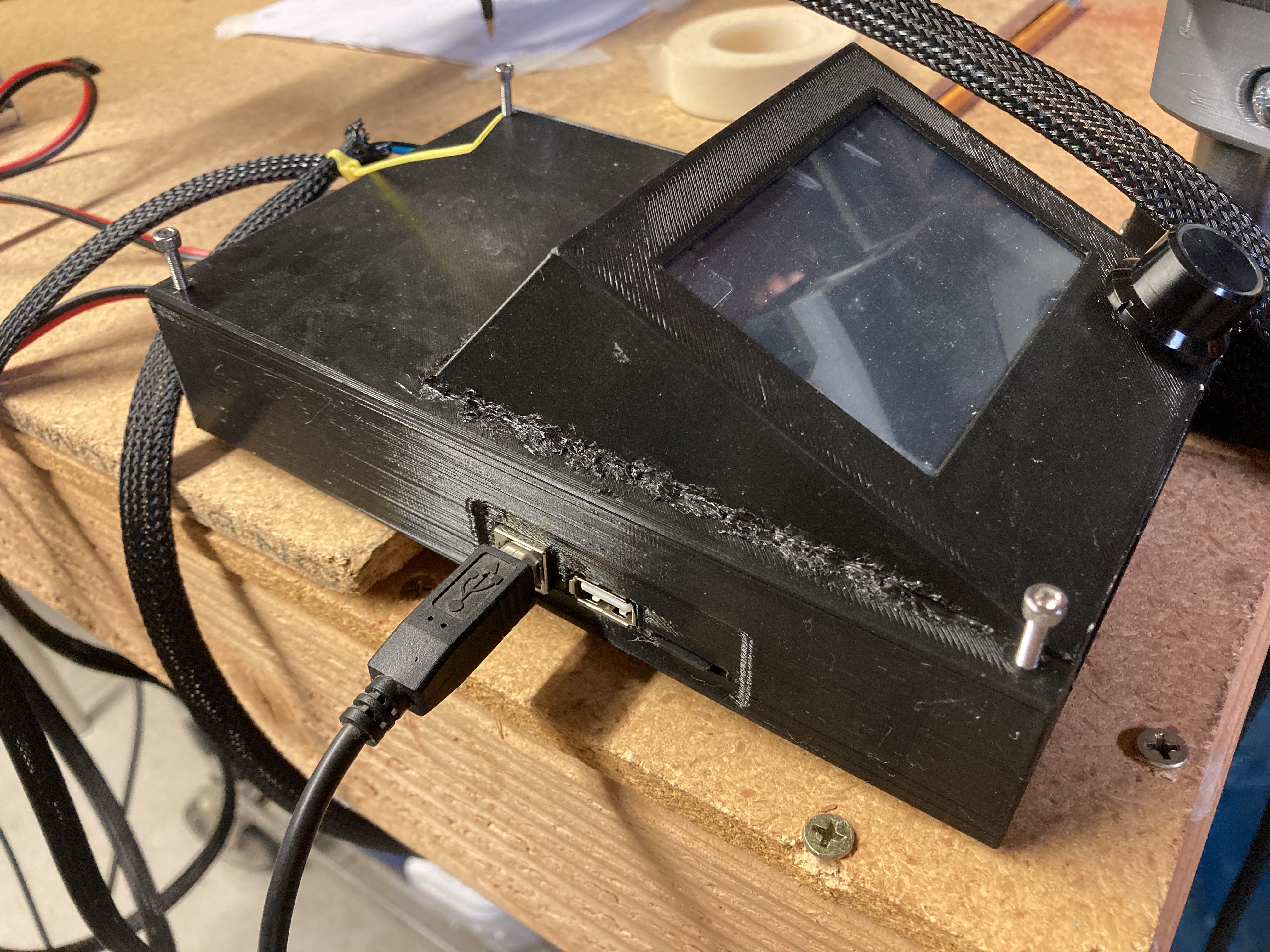
Nothing fancy. Couple small fans inside.
Still working out the top of the box now though so thats just a test panel.
Nothing fancy. Couple small fans inside.
Still working out the top of the box now though so thats just a test panel.
Files can be downloaded here:
Looks great!
Which way do the wires go/how do you have it set up on your machine? On my old build my power supply and the board were loose and just sitting anywhere, which I disliked. I’m thinking about securing the PSU somewhere, but the board’s power wires aren’t that long so I’m trying to figure out where to put the both of them.
Would you also be open to sharing the solid files for easier editing? I’m not good at all with 3D modeling but I’m thinking about moving the stepper wire hole to the side with the fans and then moving the power input (the long one?) down.
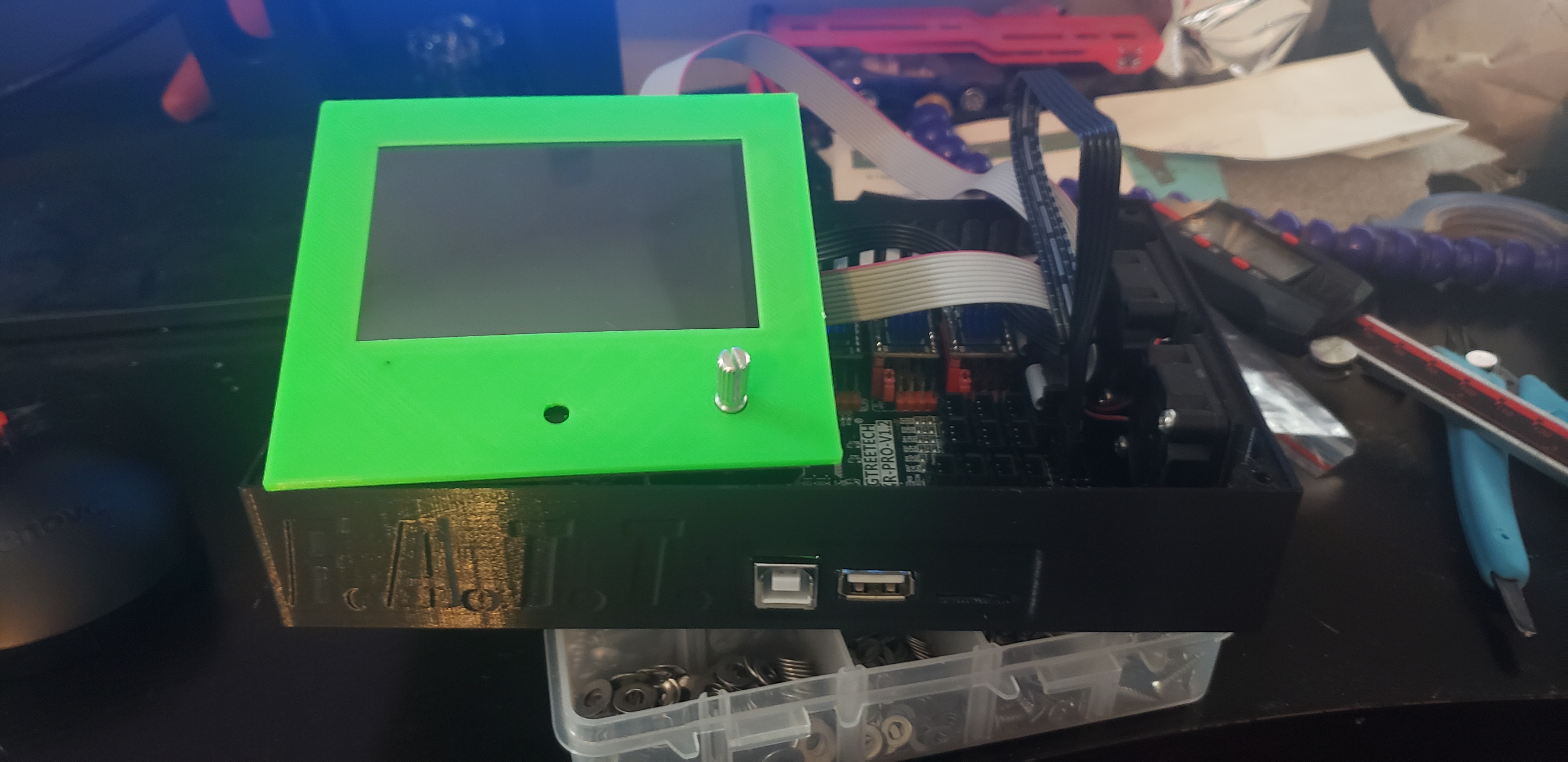
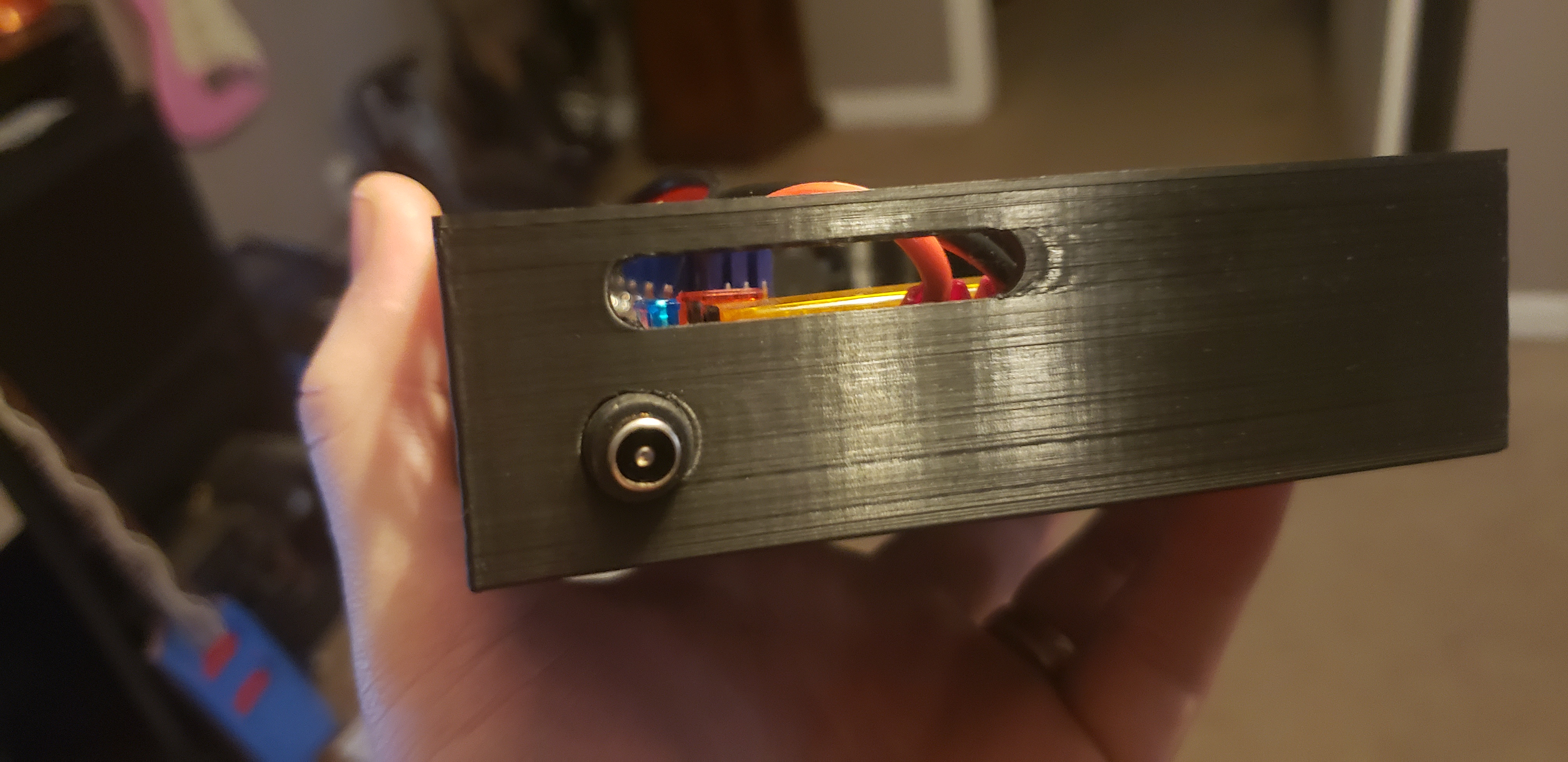
I’m using the 12v supply from Ryan. The plug adapter end goes in the small hole on the bottom. The slot is for the stepper etc…
I will put the step files somewhere for you when I get a chance
Thanks! I really appreciate it.
I’m using the 3D printer style PSU with screw terminals. I don’t really like how flimsy the 3 prong plug is coming from it (that could probably be fixed by some crimp terminal connectors), which also shortens the cord. I’ll have to look around the house to see if we have an old power supply that might work. One less box to worry about, and much more flexibility.
step files have been added to the thingiverse link
Thank you!
Started editing a bit today and wasn’t sure about the hardware. On the lid, the holes are 5mm diameter, whereas in the base they have threads and the unthreaded part is 3mm diameter. What are you using there? Some of the extra M5 screws from the upgrade kit? I guess I could try removing the thread and leaving a 3mm hole for M3 bolts.
From what I can tell, the screen holes are 3mm diameter, so use M3 hardware there?
Yeah I originally tried creating it with threads but it wasn’t going so well for me.
I have a large assortment of metric machine and regular screws that i resort to.
The screen screws are indeed m3s, the board screws are supposed to be, but i think the hole is slightly too large as the m3s stripped out on me pretty easily.
Lid to base screws i ended up using a wood screw i had laying around that fit, i think m4s are what I designed it for.
And are you using 3010 fans?
Yeah
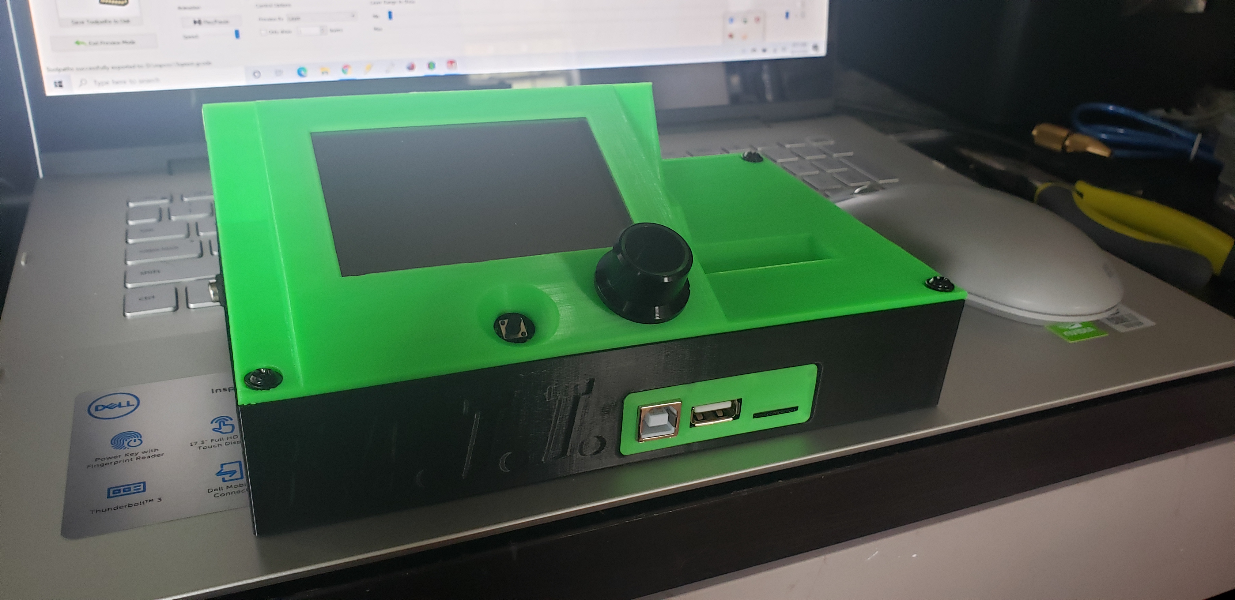
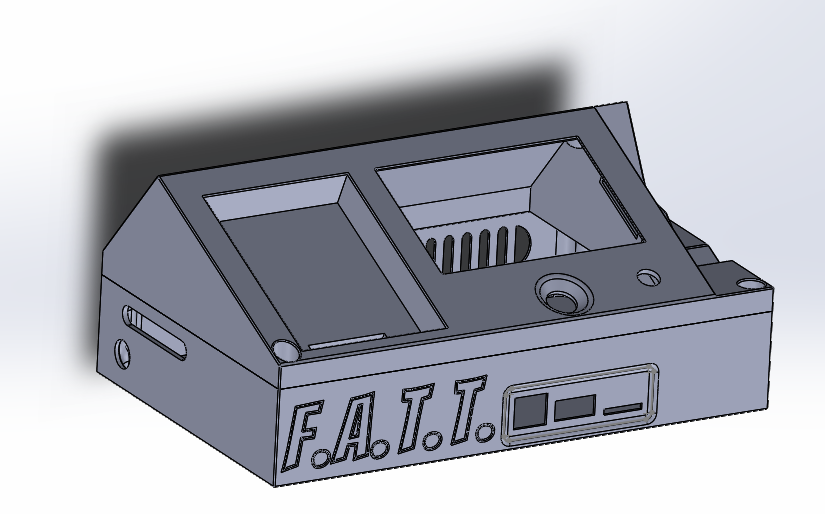
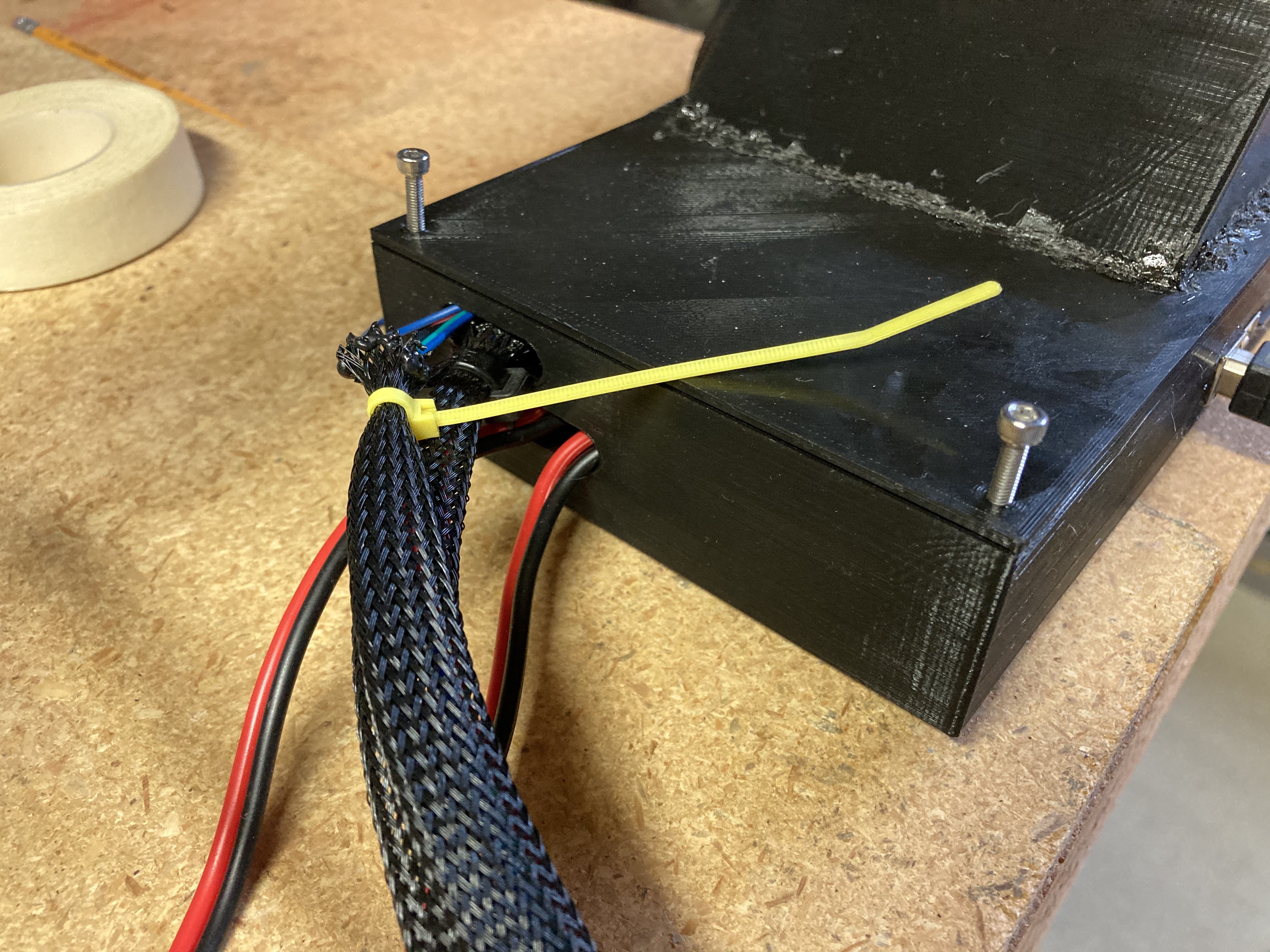
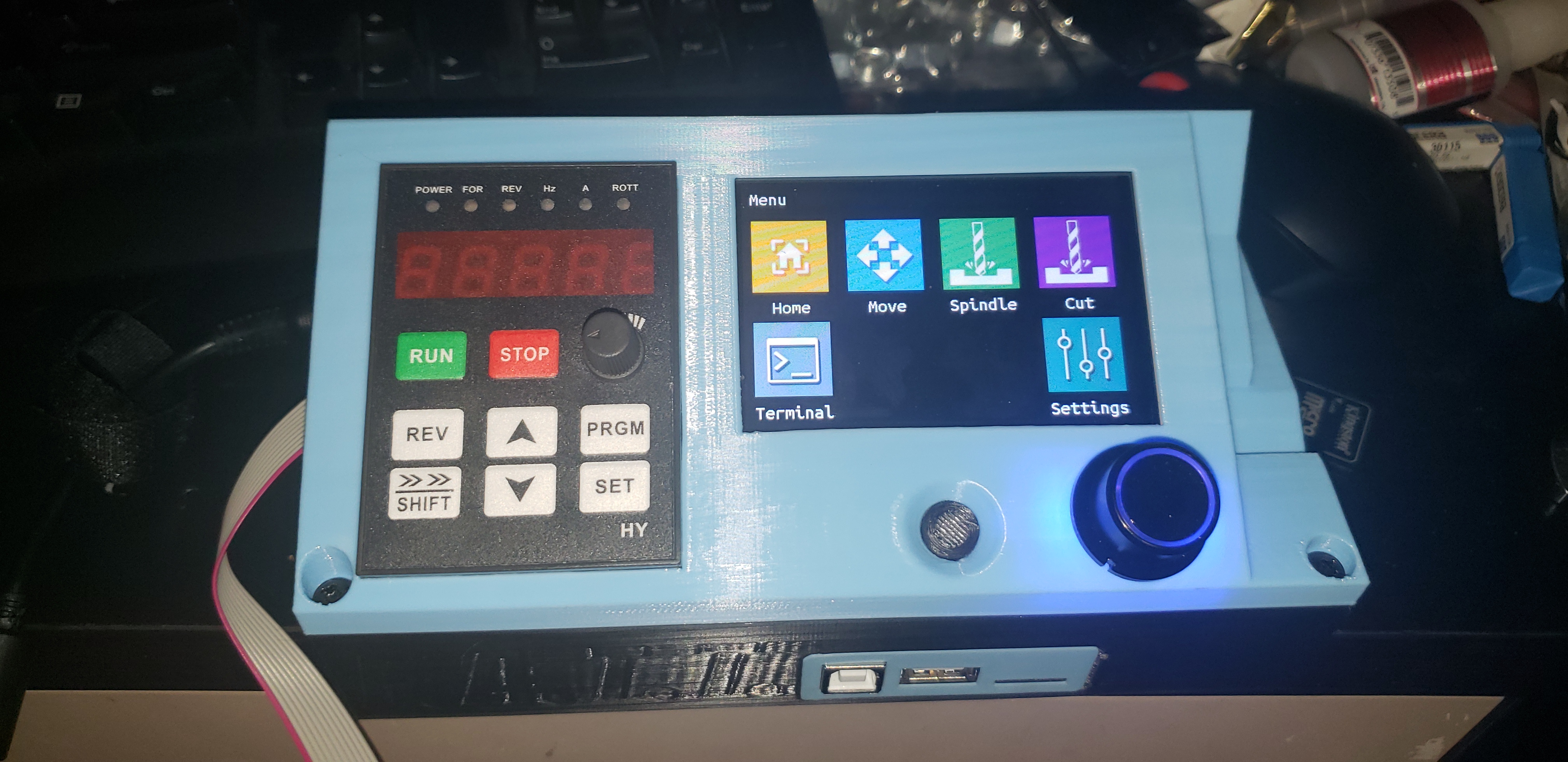
Here’s a photo of the case with the changes I made. Most notably is the rotation of the screen and removing the button layout (the way I figure, I want to mount the power strip somewhere accessible so that if something goes wrong, I just turn it off instead of reaching for the reset button on the board). Also pictured, but hard to see, is the changing of the holes on the back where the wires come out. The power opening needs to be longer and/or moved over some more, my measurements were almost close enough. The stepper opening seems to be okay. I’ll be redoing the wire braiding and zip ties with some wire harness tape, so they should be able to go inside the box easier.
I have a few changes I would make before releasing it, namely that all the holes (which I changed to 2.9mm diameter) are just a bit too tight and make it hard to put in screws. Then again, I’m confident that the screws won’t strip very easily as you noted.
Power opening is designed to fit the universal connector. That is why it is placed and sized that way.
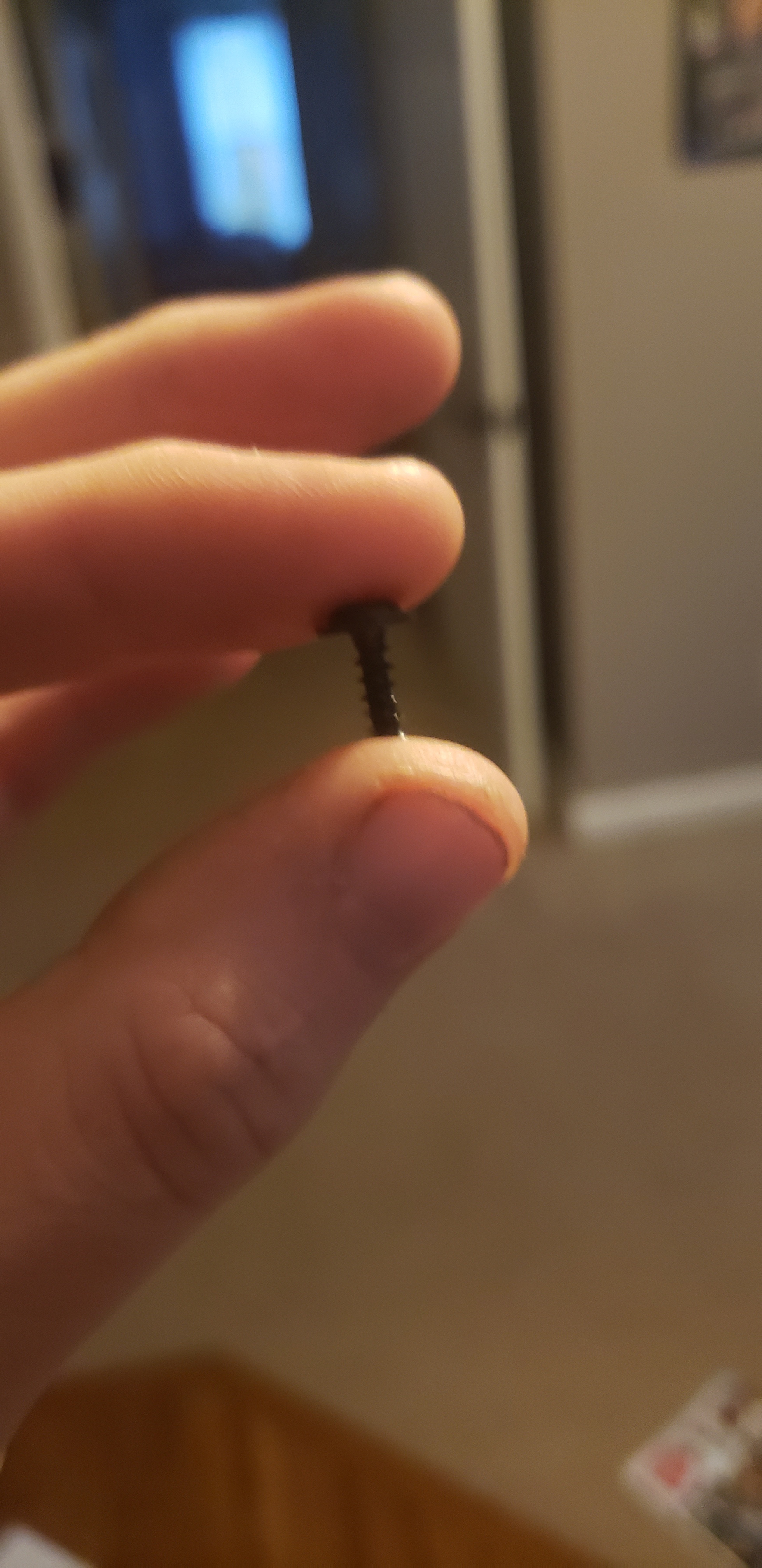
Also these are the screws u use, which is why i left the hole thst size.
I actually use the reset button a lot on the current rambo setup, im always hitting the wrong button for homing and dont have sensors on it.
i hope this fits the BTT GTR board. it looks awesome!