I bought the Burly unit a while back and only got it halfway put together before I had to devote my time to other things. I am now picking up where I left off which is trying to square the gantry. The outer dimensions are exactly the same lengths and the diagonals are as well.
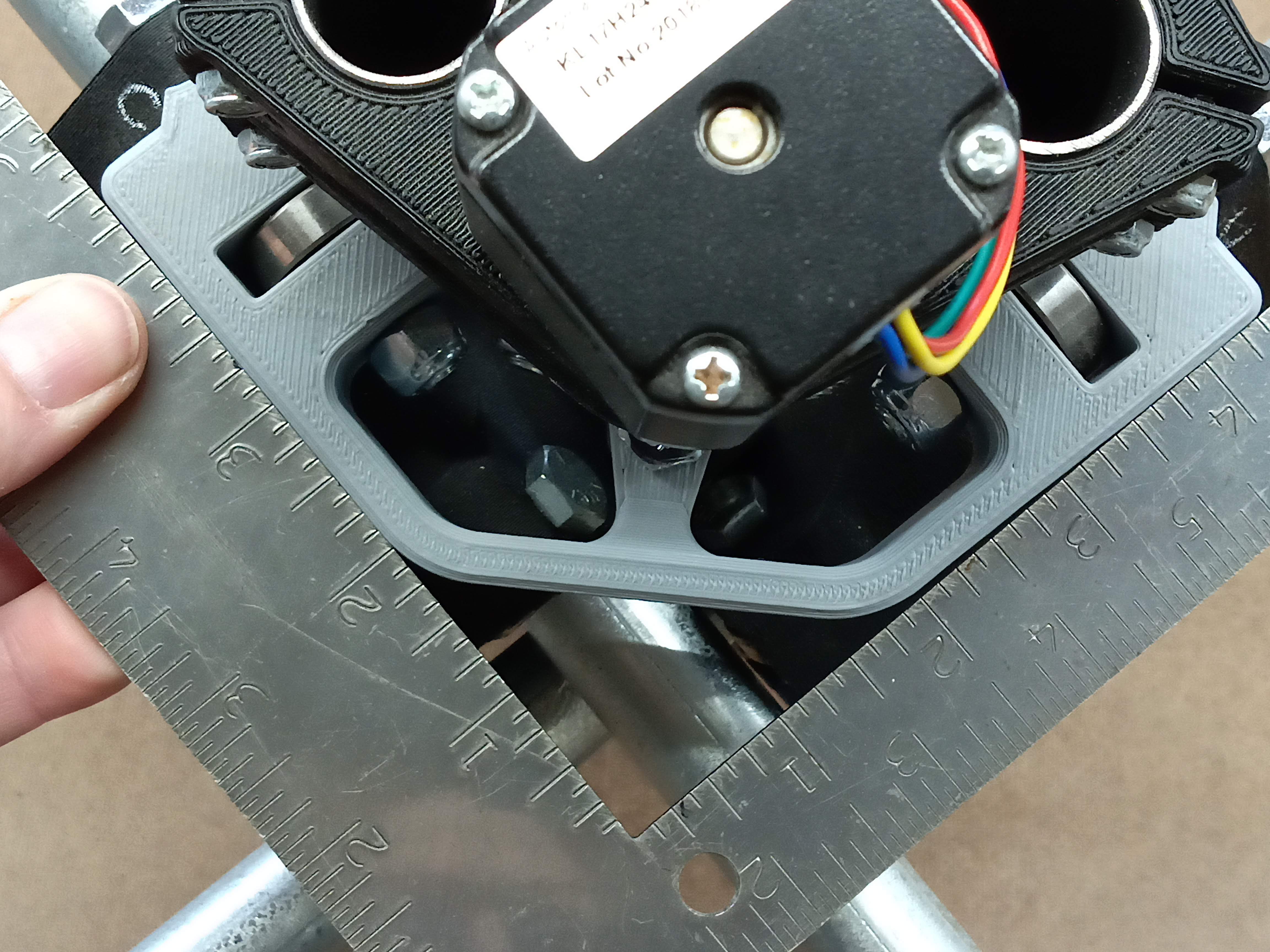
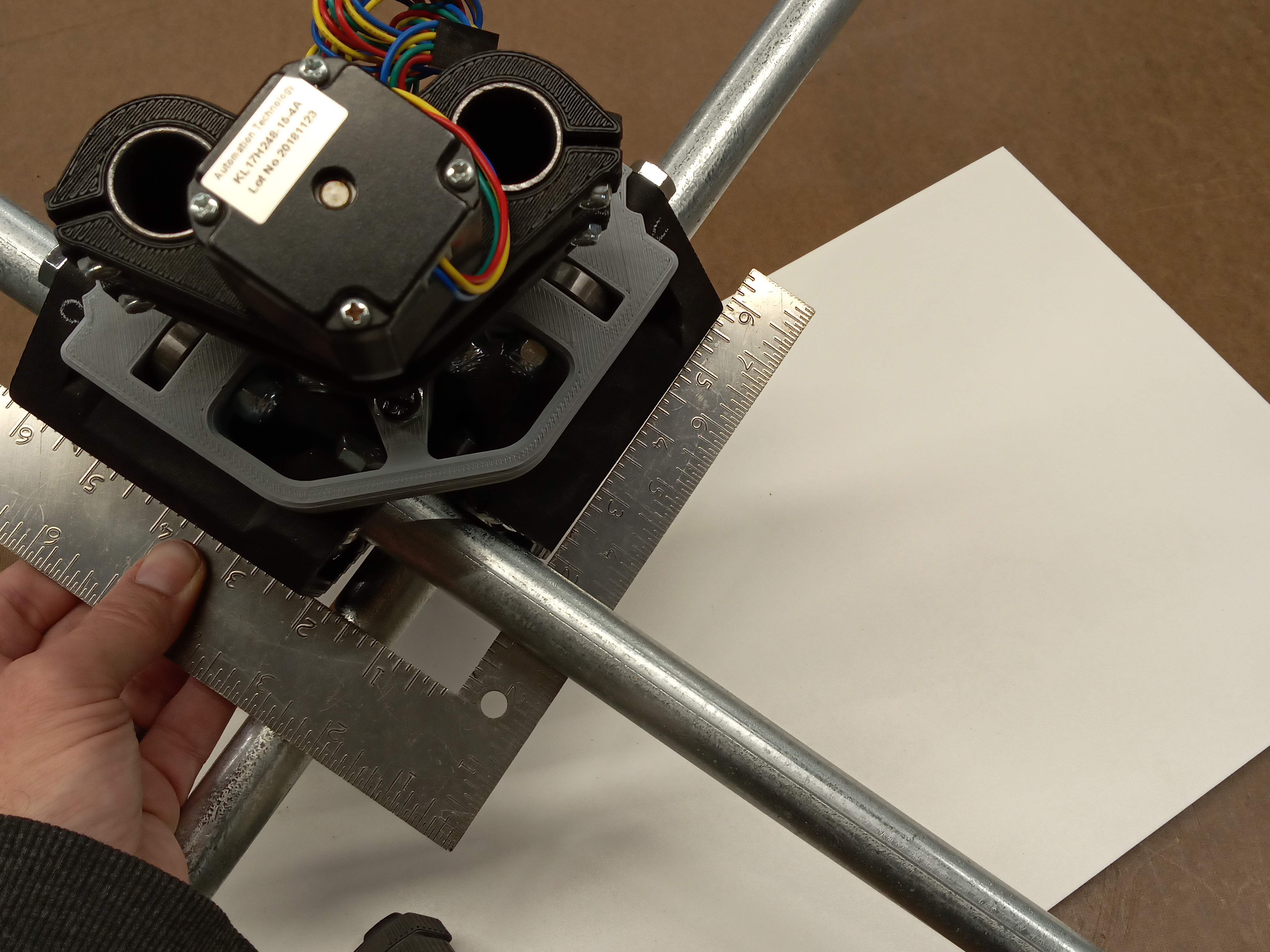
I have tried everything that the forums and the instructions say to do. In fact I have taken the gantry unit back off AGAIN to go through the setup. While having the gantry on my bench and after I have checked all the bolts and have tightened them as instructed (All tension bolts are loose) I thought I would check the squareness of the XYZ top/bottom parts as well as the XY parts that are attached to them. I noticed right away that they are far from square. In fact the orientation that they are out of square explains why the gantry rails are so far out. If you look at the pics the gantry rails are out of square by 1/8" per foot. My setup is roughly 4’ x 4’ (table size) so it is out of square roughly 3/8" (ish) from end to end. Making adjustments to the tension bolts makes little to no difference.
I don’t know the Burly well, but the out of square rails could be pulling the core, and sitting that way a couple years could make it permanent.
You should be able to make the rails square. They will pull back to where they are when the motors are powered off though so you will need to pull it back into square when powering the motors up. If you do, the machine will cut square.
It may also be possible to update the machine firmware to use the dual endstops, which will provide a method of automatically squaring the machine on power up.
Thanks for the reply Dan. I am not sure how the rails would have pulled it out of square. As mentioned the XY (outer) rails are perfectly square from all angles. Plus the trucks on the ends of the those rails were super loose. So loose that the bearings were barely touching the rails if at all.
If you mean manually try and hold the rails square while powering on, I don’t think I want to do this every time I want to run this thing.
I would rather replace the XYZ parts as those appear to be the culprits here. Is it possible to buy just those two pieces?
I used duel end stops to make sure my rails were square, and did multiple 100mm square cuts adjusting the end stops every time until i got something that was 100mm square, and within 0.2mm on the diagonals.
using duel end-stops lets you dial it in much tighter then measuring via set squares cause you can measure the cut and test. (same diagonal trick that Ryan recommends for squaring the base)
If you can’t (or dont want) to invest in the time (and electronic cost / firmware pain) to do duel end stops, one other method that could work (although I have never tried it) is to put stop collars on the rails, and push the trucks hard up against them when you start a job, and make sure they are square (would likely need to do the same cut, measure, adjust thing I did with the end stops)
that way you know the machine always starts square, and as long as there is no missed steps, it will stay square.
The Lowrider uses this trick, only the hard end stops are built into the design
The reason is because when pulled to that corner both rails hit the opposite corners first so all I have to do is pull the gantry snug into that corner and turn it on. Where if I did any other corner I may have to reach to try and pull other corners tight as well.
No it does not matter which corner you square to.
I squared mine to the front left, but thats just cause my machine is boxed and its the easiest corner to access
If you’re talking about auto squaring using endstops, then the firmware is set up to home to the 0,0 corner. If you use the far right, you either need to know that in your cam (your designs will be rotated 180 when you carve from estlcam) or you need to change the firmware to home to max and probably a few other small items.
I would suggest just homing to the closer left corner.
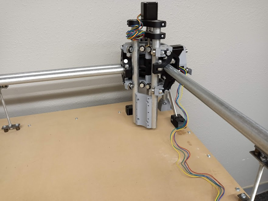
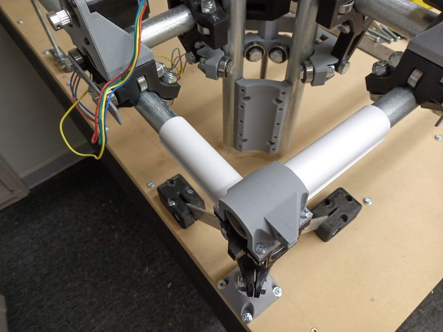
So I finished up squaring XY rails and installing the stop collars to manually square the gantry rails, but now I am trying to figure out how to square the Z rails to the workspace. As you can see from the picture it is angled to the side slightly (about 1/16" per 4"). I have tried using the tension bolts with no change. Honestly I have yet to see any adjustments using the tension bolts. I have also checked that the two rails are square with each other.
the other thing that may help is very slight up or down movements on the corners, but keep in mind that a very small movement there will rapidly add up to a really big movement over the length of the rail.
You could correct. Although I did check the squareness in multiple locations on the workspace. Granted there was some slight deviation, for the most part it was still out of square in all locations. The way I built my workspace I was planning to cut in a stepped workspace as you did. I guess I will see how it works the way it is and look further at it later if needed.
Facing the spoilboard there can help a bit, but it won’t fix tramming problems that such a big angle from z can cause. You will see it when you face if it’s off… cuts will feel “wavy” as the mill cuts the face at a slight angle. So after facing it is always best to verify the tramming is also square. You can adjust tramming on the mpcnc by shimming the router mount.
If it is faced then trammed… having the z gantry off angle can still result in z error. Actual z travel = desired z travel * sin (90 - z error angle)… but z could be scaled to achieve tolerances if needed. If that is done, there is still a slight xy error but probably within tolerance for most parts (otherwise again, this linear offset can be factored into cam output).
Thanks Kev for the info. The more I think about it I can see your point. Not sure exactly how I would shim the router mount to correct that specific angle. Will have to think about it some. Any examples/ideas would be helpful. Thanks again!
I tried shimming the router mount by putting a folded piece of craft paper between the router mount and the conduit but I don’t see how this will correct it. The side where the gap is at the bottom I shimmed the bottom screw on that side but left the top screw alone. This tweaked the conduit a little between the screws but not sure how it affects things above the router mount. This did not affect the opposite side. Not sure if I should shim the top screw on the other side or what?
Also by doing it this way it seems to put stresses on the printed mount when I snug it up. I start to hear cracks. I have already broke one of the feet on this and I really don’t want to have to print another part. There has to be a better way to correct this issue? Maybe I am not doing it correctly.
Be wary anytime you hear a crack… never good on printed parts tbh. Inspect the part carefully with a magnifying glass; even the smallest hairline crack will be a big issue later on.
Sounds like you are going about shimming for tramming correctly. Since there are many ways to mount a router to these things, there are almost as many ways to shim the mount. In my case I made a mount that clamps around the router. To square up tramming, I had to play with brass shims, putting them in the corner of the mount as needed to tweak it straight. In my case only a tiny shim was needed and nothing close to cracking for tightening. See if there’s something else you may want to adjust to get it closer before tightening on the shim. The idea is minimize how much the shim as to do, to reduce the stress that shim puts on the mount.
Also a side note: brash shims are of course better than paper, and they are something you will want to have around when you do machining in general. You may want to get an assortment pack of k&s shim brass next time you go to the local hardware store… you’ll need it for more than tramming.