I build the l3 with SKR Pro 1.4 with 2209.
All works fine until I started to do the gantry’s.
The insides are milled first and look good than the first pass of the outside is milling around the first mounting holes the 2nd pass is milling the mounting holes completely……
2 issues here.
First during the milling Y1 seems to do +10mm from the original home point (start of mill). Is this due to the force of the spindle in the wood creating offset?
2nd issue.
When I started testing where the issue could be is that on each Y travel Y1 is spot on but Y2 gets a +5mm offset per back and forth travel.
I can understand that the tension on the timing belt always introduces a little difference in length (my build Y=2500mm).
Is there a way to set steps per mm for Y1/Y2 separately?
Or do i need to approach this completely different?
(Ps did the sizing, squareness and swapping Y2 driver with X driver)
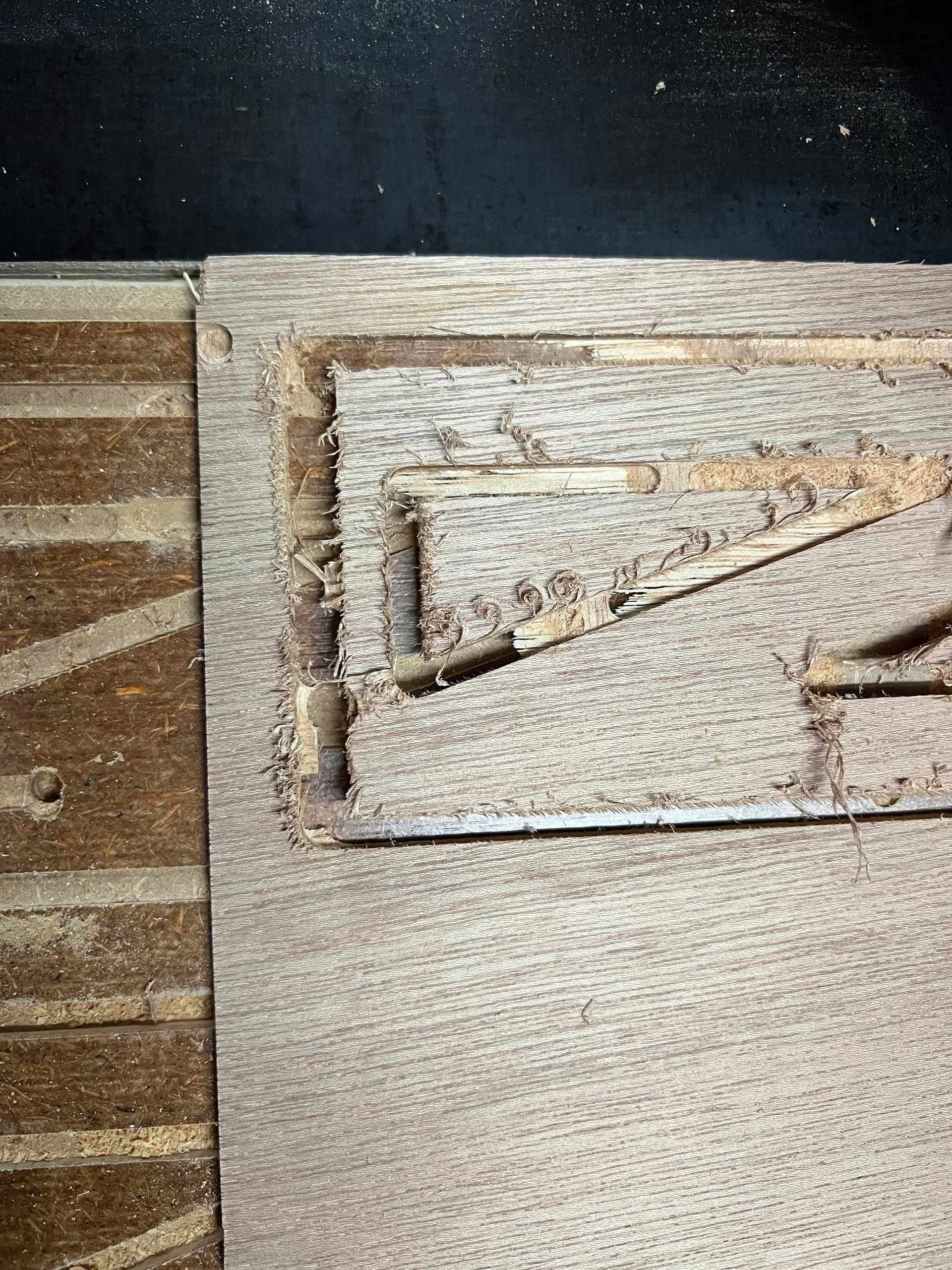
It might be overtightening of the screws. That looks like lower density than MDF, more like regular particle board, which can be rather weak in thinner sections. It looks to me like the bolt for the roller assembly and the bolt for the Y drive aren’t parallel anymore.
At the very least, your YZ plates are going to need to be replaced.
I would recommend that you look at 12mm (1/2") plywood, or at least MDF material for them.
You should absolutely NOT need to set steps/mm differently for Y1 and Y2. Something is happening to your machine in use that is causing this to have trouble. Until you have a repeatable operation where the machine is returning to the same point as it started, you cannot determine the accuracy of your steps/mm. The machine travels the same distance forward as backwards, so if that’s not the same, something else is happening, and needs to be addressed first.
So things that you can do:
Slow down the cut. Less resistance on the cutting bit will reduce the tendency to lose steps. You can also try reducing the depth of each pass for the same effect.
Make sue that your mills are sharp.
Try to have as even tension on the belts as possible. The belts should have tension, but should not be stretched. It is probably easier to start loose, and then tighten until you eliminate backlash – that is, when you move the machine forward and back it returns to the same place as it started, every time with several repetitions.
Check the current settings on your firmware. I don’t know the SKR 1.4 (AFAIK, there no SKR Pro 1.4. There is an SKR Turbo 1.4 and and SKR Pro 1.2.) V1 firmware sets motor current to 900mA, personally, I found that a bit weak for X, and have mine at 1100mA, and 1000mA for Y1 and Y2.
Check that your motors are appropriately rated. The ones that V1 sells are (IIRC) 76oz in, and are the ones on my LR3. My Primo uses 84oz.in motors. If you’re using V1 supplied motors, you should be OK for available power. If not, check the ratings on your motors. More torque is OK, but might require higher current in order to achieve that torque. You don’t need (or want) full rated current, but probably want about 50% of the full rated current.
No matter what though, those YZ plates look to be finished, and should be replaced.
Unlikely. The motors are more a cause of interference than affected by it. EMI usually hits things like the endstops, or other sensors, caused by the choppy waveform sent to the motors. Maybe something like the piwer cable to the router cound interfere, but it wouldn’t be subtle at all if so.
That picture looks much more coarse than the MDF I get here, like regular particle board. MDF gets much stronger if you paint it, but once cracked like that, it will need to be replaced. That shouldn’t cause the problem though, but could affect tracking. Cuts parallel to the Y axis might wander a bit. If you replace those parts with similar material a coat of primer would probably help prevent the same problem again.
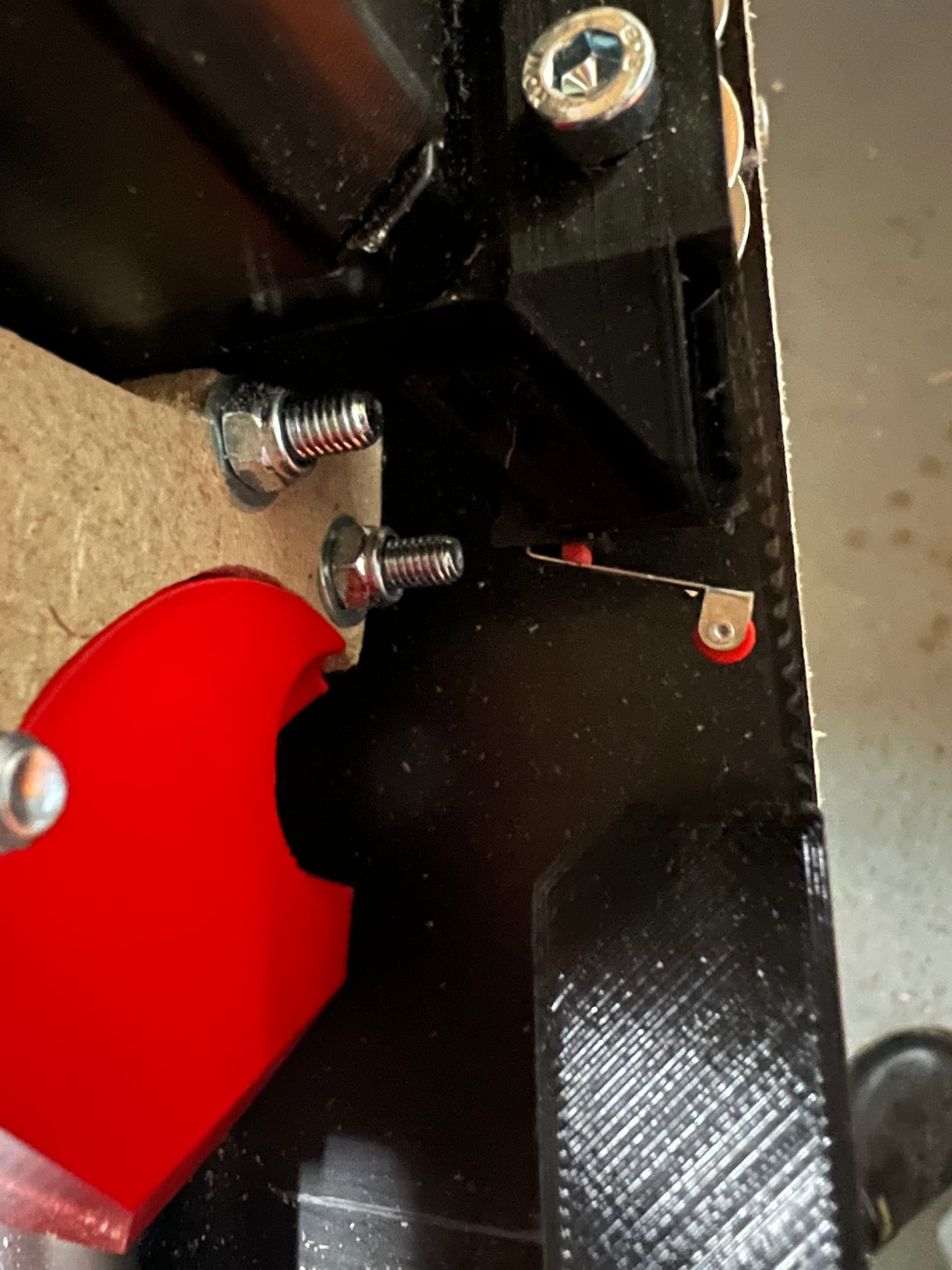
I can’t believe I didn’t ask about grub screws… Must be losing it. Make sure they are on the flat part of the motor shaft, too. Once you’ve added loctite it’s hard to move 'em, but if they aren’t on the flat part of the shafts they could cause a problem.
You can also try resisting the router motion with your hands to see how much pressure it takes to make the motors skip. It won’t harm the motors tk do so, and might show where something is weak.
But the back and forward travel is not!
If I move 2000mm forward and back I have a 5mm difference from the starting point (its 5mm of the stop).(and every travel afterwards @ an extra 5 mm)
I have taken all apart, Double-checked the Scrub screws (Taken them out and put back together).
I have checked the YZ plates and it looks worse @ than it is all is firmly in place and lined up as supposed to.(Planned to replace them when I can do a decent mill)
Checked all the wiring.
Checked all the connections
Checked the tension on the belts.
Played with the current 900-1200mA and returned everything yo 900 as that seems to be more stable).
Updated the firmware to stock ( I had a firmware with larger bed size)
The 2000mm travel is correct sizing wise but return is not.
Could it be that the tolerance on the motors is too big? (Weird that they are in sync).
Have the same issue on X
Z Looks to be good (travel to small to measure?)
Motors stepperonline 17HS19-3004S1
Driver BTT TMC2209 V1.2 UART
SKR Pro V1.2
Belt GT2-10 aramid fiber
Since you just reflashed, it’s probably not the firmware, but I think it’s time to start isolating components. Swap what you can from one side to the other until the problem goes with it.
Example: Have you tried swapping the wires from y1 and y2? You can do this at the board (after you turn it off of course).
I had a weird issue with some external drivers that would never send the router back to the same point and had to replace the whole lot of them. Of course, I’ve never heard of it with 2209s (never heard of it with the other ones, either, lol), and I’d be surprised if this were your problem but it’s easy, free, and fast to try.
Since you’re only seeing an error in one side, you can swap the two at your board and at least eliminate everything before the plugs if the error stays on the same side (or after the plugs if the error goes to the other side).
Caution: don’t home like this unless you also swap the endstop plugs.
Thanks.
Maybe I should have started a new thread but for the sake of clutter
Right now the issue is NOT the Y1&Y2 moving synchronised.
They do but if I move Y for 500mm and return to 0 its has an offset of +5mm on BOTH Y’s
The same thing for X it does NOT return to the same place…
I have just swapped the motors Y1>Y2 Y2>Y1 no difference (And now back in original position)
I have swapped Y1/2 driver boards with Z 1/2 driver boards > no difference.
as it seems to be on both Y & X (Z not measurable) it seems to be board/Driver/Motor?
Is there any way to check how the SKR gets feedback from the driver?
Oooohhhhhh, BOTH motors are off…
Do you happen to have any spare drivers? If the problem IS the drivers, it’s likely to be the batch, so swapping one for another on your board would look just like you’ve seen.
My understanding is that you home, move 2000mm, return to home, measure error of 5mm. If you move another 2000mm and return, is the error 10mm?
When you say stock firmware, you mean Marlin? And when you home, it sets the coordinates to 0,0 at the switches? Also, do you travel back with something like G0 X0 Y0 or by jogging? Does it make a difference if you try both?
I don’t believe the board gets feedback from the drivers, but I could be wrong. I think it’s a one-way instruction.
Also hard for me to imagine how the board would fail in one stock but not the other predictably.
5mm is huge for the software and drivers. I just don’t understand how this is happening.
I don’t believe the drivers are to blame. The extra empty port is not the problem. You can swap the drivers around to check.
Can you reset the eeprom settings (M502 then M500)? That will clear out any personal settings. The firmware works already with that board, so if it is one of your personal settings, then this will help you find it. Maybe the top speed changed in your version of the firmware?
While we are on the subject, if you’ve built your own firmware, try it with the one we provide at MarlinBuilder releases.
I do vaguely remember a case where the microcontroller started stepping and the driver want enabled yet. That shouldn’t happen, and it shouldn’t be able to move 5mm before they enable. I am very confused by this puzzle.
I really hope it is something silly. Like an assumption that is wrong somewhere.
Ok this is what I did:
Did the m502 m500 > stored
Reloaded stock firmware
Did the m502 m500 > stored
Home all
Moved z-50 (te het the pen above the measuring tape
Moved Y +500
Moved Y 0 (both thru the graphical move interface)
I get a +3mm on 0
I entered the steps per mm for Z (70.39)
Homed Y
Moved Y +500 (it actually moved 500mm spot on)
Moved Y 0 and got a +2.5
Homed Y
Moved Y to +2000 (spot on again) (now with gcode in terminal)
Moved to 0 and I get a+6 on both sides….
Motors sound good on travel (no interruptions, nothing that’s dragging on the gantry)
I’m slightly going mad
(This has to be something really stupid…)
 )
)