Hi everyone, I’ve been lurking for a while. I’m Yvan (pronounced Why van?) and I’m a Controls Engineer at a self-driving industrial robot company. My wife-unit and I also run a small farm with chickens, goats, ducks, bees, and god knows what else.
I’ve been holding off on posting this until I had a chance to clean up my shop. It was pretty bad. I am pleased to share that my LR2 is 90% complete, and fully functional. I call it the mostly-free CNC because I’ve been pretty good at scrounging parts from all over the place.

The reason I built this is that when I said I wanted a farm sign my wife got quotes in the $700-2000 range, and I figured I could design and build a CNC for $500. Then I found the LR2, and I skipped the design part.
Things I got for free/cheap
- table/workbench is made from a 2x4 construction shelving unit that I disassembled from my old house
- 50 year old Sears router from my late dad
- printed on various colours of filament that I had kicking around
- Arduino Mega I had kicking around
- power supply I had kicking around
- metric bolts from work
- MDF and plexiglas I found in my shop
- small shop vac from my late father-in-law
- Raspberry Pi, which I accidentally smoked with 24V

- tractor inner tube for router guard/dust barrier
Things I paid for
- roller wheels
- GT2 gears and belts
- stepper motors
- cheap RAMPS clone
- stepper drivers
- limit switches
- tubes
- casters
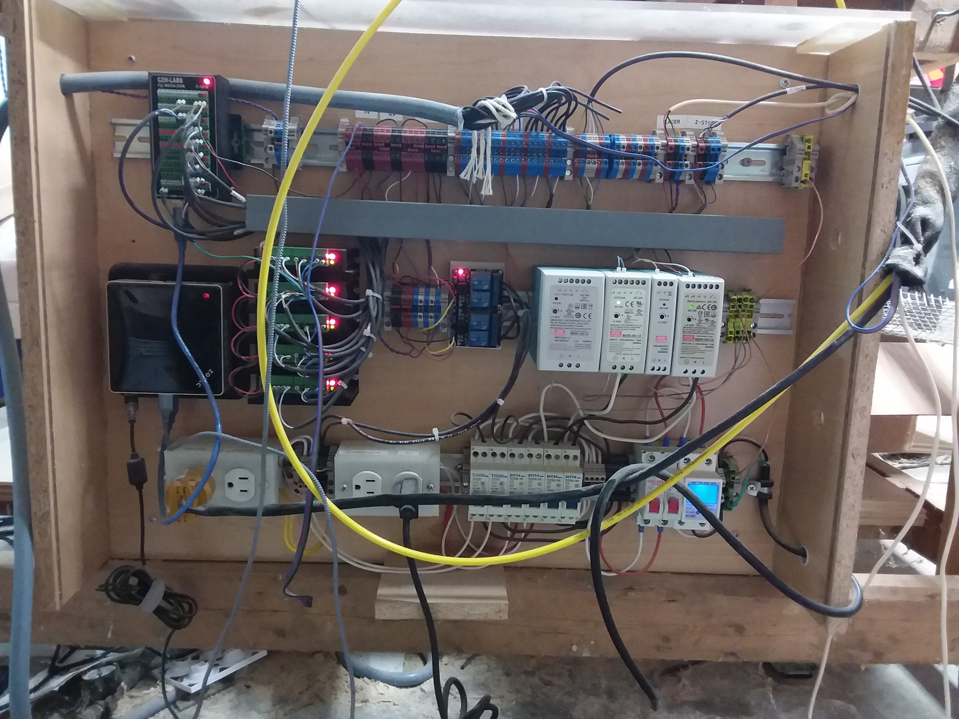
- miscellaneous electrical panel stuff.
The important details
- Workpiece size: 4 ft x 8 ft x 50cm
- Table: 2x4 softwood ladder construction
- Top/spoilboard: None, I’ve just been screwing into the frame
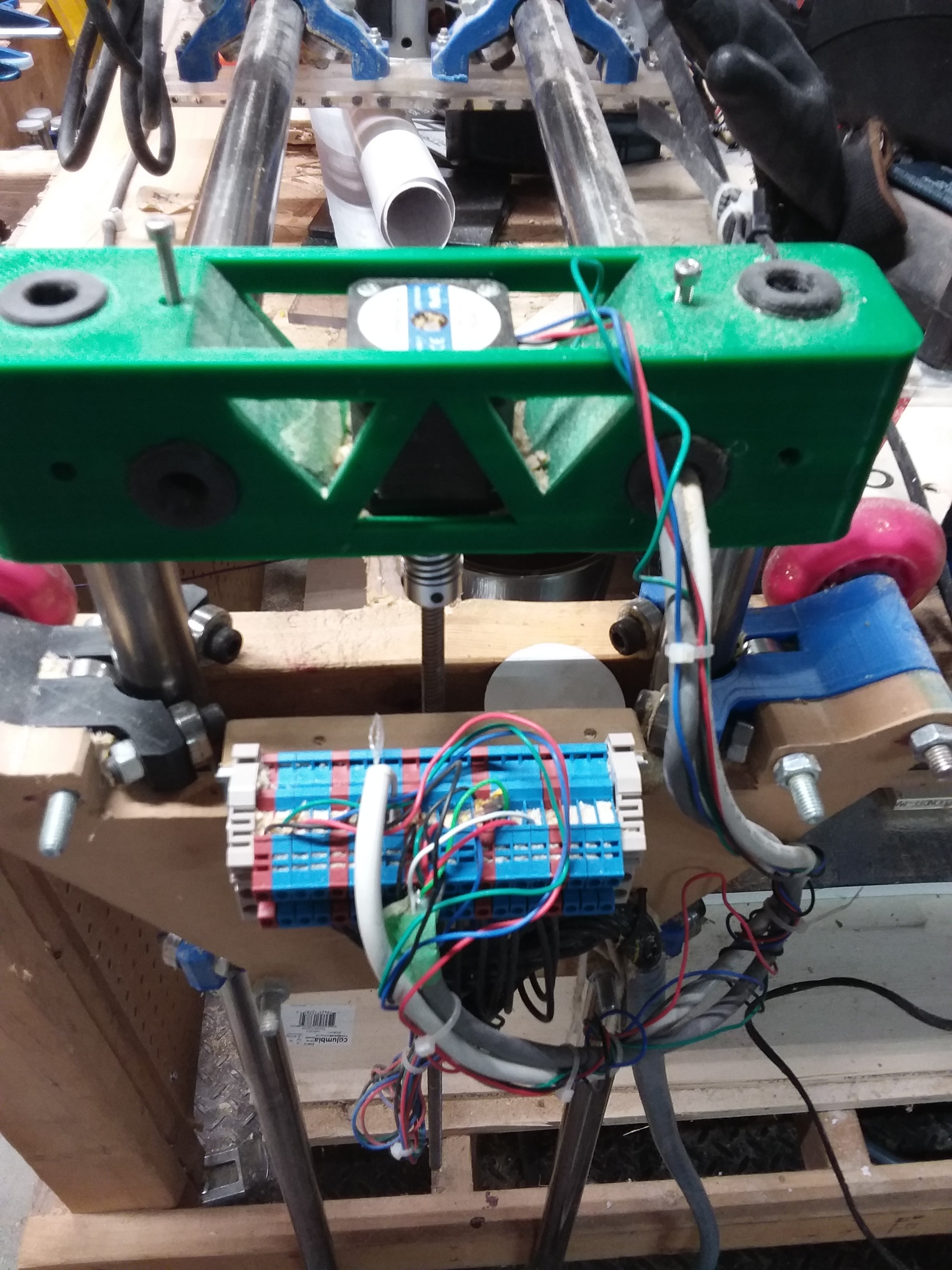
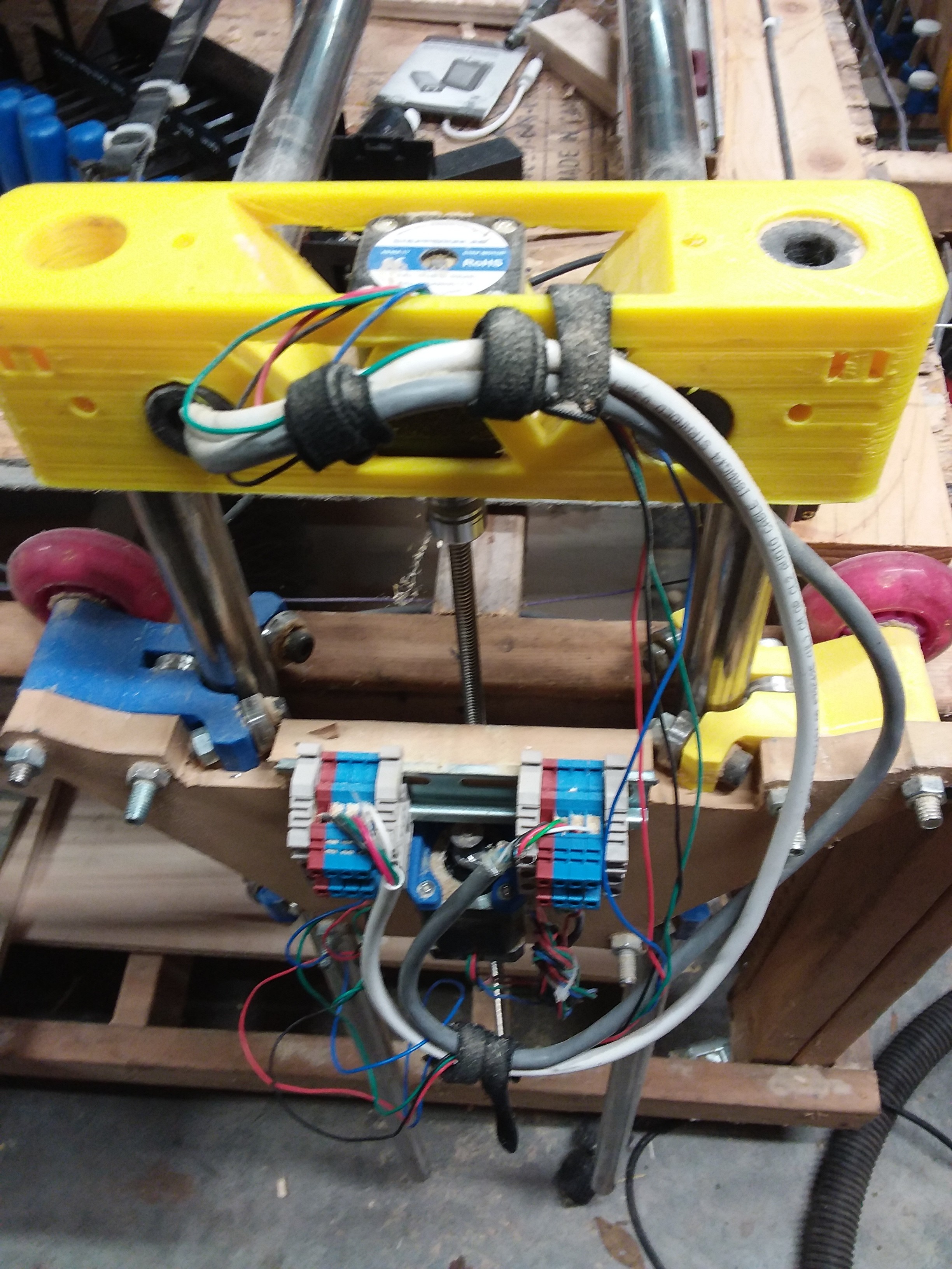
- XZ plates: Crudely sawn 12mm MDF
- Router plate: Crudely sawn 6mm plexiglas; design modified to accommodate my router and vacuum
- End-stops: One at each end of x-axis at the moment.
- Controller: Arduino+RAMPS with DRV8825 (?) drivers
- Wiring: X and Z are in series. All connections are broken out to terminal blocks for ease of assembly and upkeep.
- Display: None at the moment. I have one of the common ones but need the PCB to convert the two 2x5 connectors to the RAMPS board.
- Interface: OctoPrint running on FreeBSD on a nano-size x64 PC
- CAD tool of choice: Fusion 360 for personal; Solidworks for work
- CAM tool of choice: Fusion 360 for most stuff. Easel is OK for quick and dirty jobs.
On the to-do list
- Make the cables, hoses, etc. pretty
- 7000mW laser is on order
- add extruders
- a drilling attachment from doner drill
- cubbies for all my power hand tools underneath
- drawers for mill tools and filament
- area for sheet storage and off-cuts
- relays for router, vacuum, etc.
- motor speed controller for spindle
- Maybe one of those 9-axis SKR boards so I can separate X and Z axes and still add extruders.
Handy pegboard at one end


You may have guessed that I’m a function over form guy.

Mini PC and RAMPS


These will be going into a cabinet so they don’t keep getting filled with sawdust.


Things that surprised me
- The zip ties are fine. What is everyone bitching about? I didn’t have the dexterity to use the little D-shaped bits though.
- I tried mounting the controls to the gantry like most people, but I just found it awkward.
Things that enrage me
- When the power is cut, one side of my z-axis falls, making it a pain in the ass to reset. Thankfully my tubes haven’t bent yet. I think I need to add some friction to the one side to avoid this (in addition to having already disabled the
M84timeout. - Until you clean up your cabling, it is really easy to CNC cut your y-axis stepper cable.
- Those Dupont connectors are the worst. I’ve gotten pretty good at crimping them and making connectors, but I rage-quit and replaced them all with terminal blocks (except to the board itself)
- I have yet to find CAM software that doesn’t choke on my farm logo (or more generally on semi-complex SVG files)
Anyways I hope to actually make something pretty to post here soon.