I have been having intermittent issues that are becoming more frequent on my LR3 SKR 1.2 Dual End stop build.
When homing the z-axis, on the Xmin side it will move up, trigger the end stop and immediately fall down, and then start winding back up, hit the top, and fall back down again. Grub screws are tight.
Your failure points are the control board, the stepper driver, the wiring, the stepper motor, and a mechanical issue. The majority of the time with issues similar to yours, the root cause is mechanical, but I cannot make a mechanical problem fit with the behavior. An intermittent wiring issue does fit the problem, and is the most likely culprit. It is rare for the stepper motor or the control board to fail.
If the problem occurs regularily, you can gain insight by swapping things around. For example, swapping the Z1 and Z2 cables at the control board and testing can indicate whether the issue is a driver or a control board issue, or whether the issue is downstream.
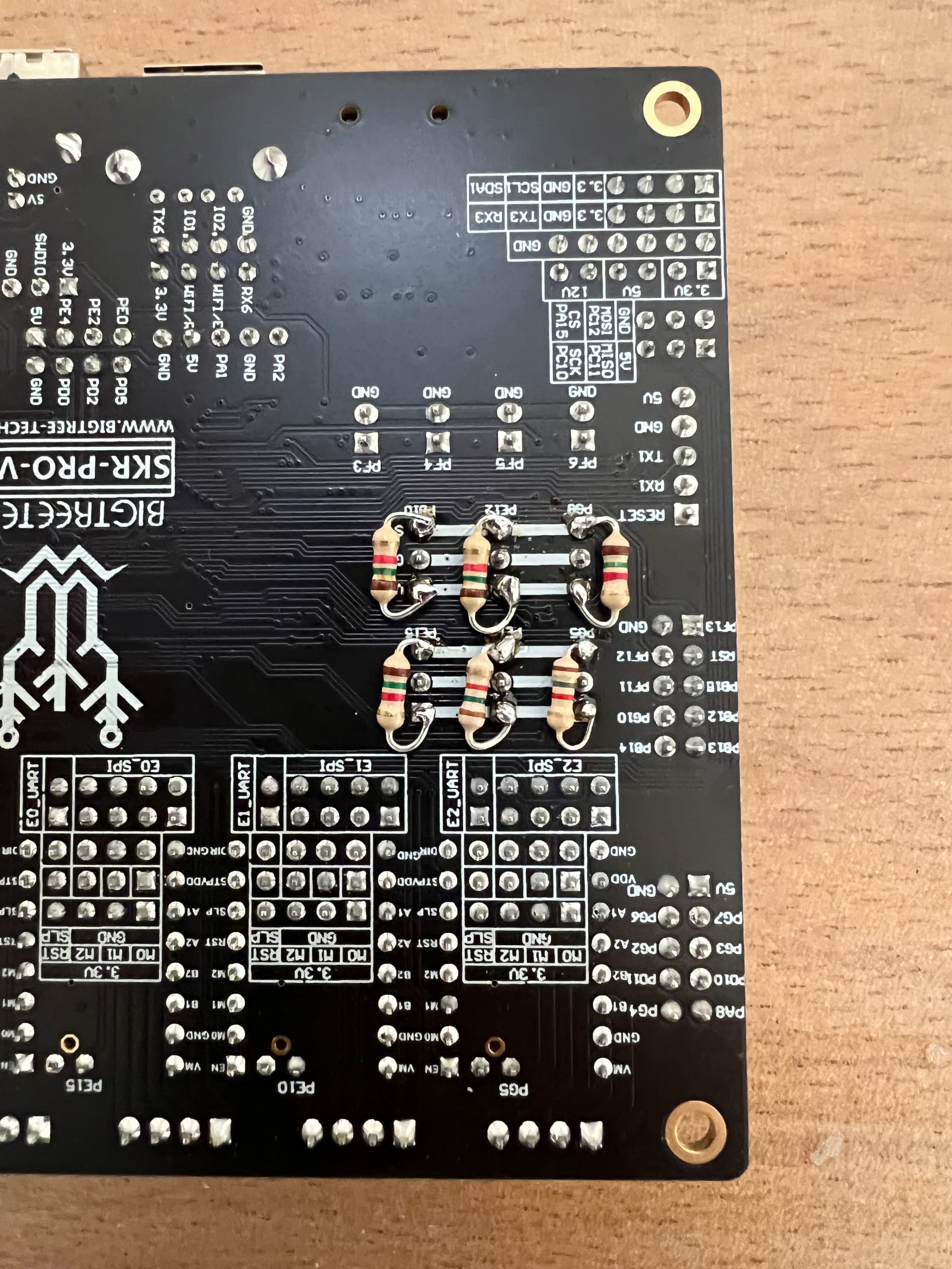
Had the same issue using a SKR Pro 1.2. Root cause was the board, the end stop did not trigger. This behaviour was not consistent, ie sometimes homing worked, sometimes it didn‘t. Soldering additional pull-up resistors to all end stops solved the issue.
Small update, noticed similar behavior on the Xmax side whenever the router was on that side. It only does it when it hits the end stop, and when it starts the reverse motion to drop the gantry slowly to trigger the end stop again, it drops down. It eventually catches itself and starts to come back up, but when it triggers the end stop it doesn’t stop, it crashes into the frame and drops back down, rinse and repeat until I hold it up from dropping, it eventually catches itself and homes correctly.
Do you have any images showing the resistor installed? What size did you install?
I’m not an engineer, but I am a very fast learner. From what I was reading about the getting rid of the LED it solves the issue, but i want to keep my LED for function check purposes.
I just checked the voltages coming off the board for end stops, all at 2.03v when activated.
If I’m understanding this correctly, we just need to add a resistor coming out of the #3 pin on all end stops? I actually found a box of resistors randomly lying on the side of the road the other day. I’ll test them and give them a try.
A pullup resistor would be wired between 3.3V and the signal pin (between pin 1 and pin 3). I believe a 1K resistor was used in the first post I read on the issue.
Steve Ulrich used 1.5K according the above post, and I did the same. Works fine for me. 2.03V was exactly what I measured, and this is not consistently read as a HIGH signal. Sorry can‘t send you a picture now as I am in a middle of milling my wasteboard, but will do as soon as I can. It is simply soldering the resistor as Robert wrote, on the soldering side of the board.