TL;DR I got only a 4mm cut when I was trying to get a 5mm deep cut.
Long story:
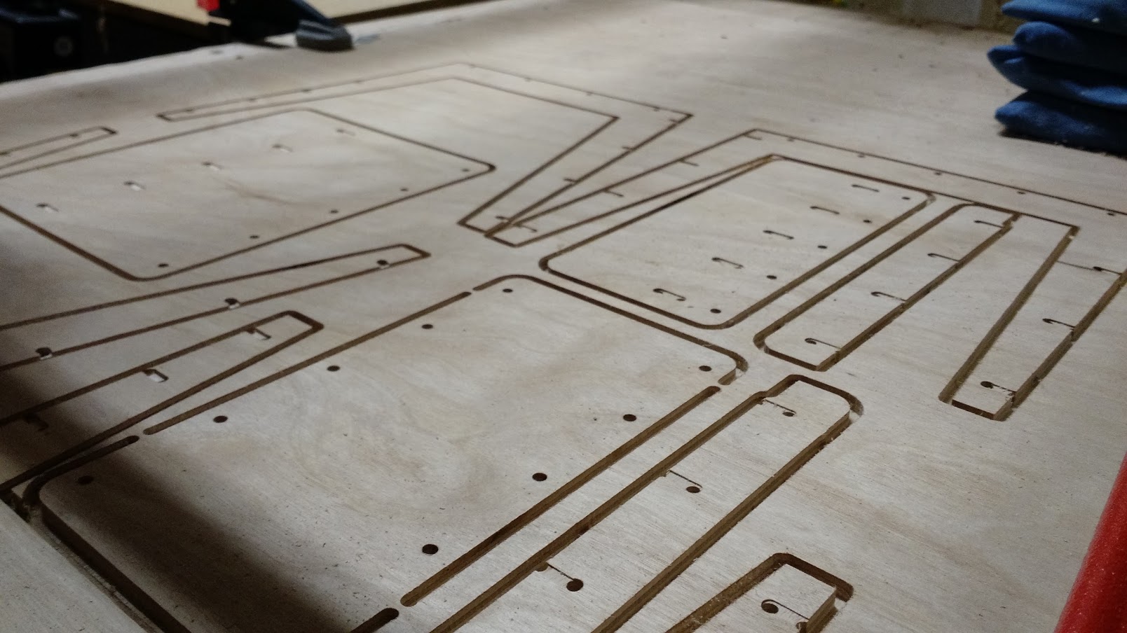
I am cutting some plywood stock. I measured it with my micrometer and it was about 5mm (4.9-5.05 measurements). I set the depth of cut in estlcam to 5.1mm to make sure I make it through. Looking at the gcode, it doesn’t look like a CAM problem. The Z-5.1000 is in there a bunch.
Before the print, I moved the Z axis down onto the 0,0 location, and used a piece of paper to make sure it was just above the surface of the wood.
After finishing the program (everything looked great, the downcut bit is awesome) it became obvious that it did not cut the entire 5mm. I cut one piece out with a knife, and measured the thickness again, and got 5mm. I measured the depth of cut, and I got 4.0-4.1mm.
Bummer.
So I moved the bit down to 0,0,-1 mm and reset the home position, and ran the program again. This time, it just kissed the spoil board.
What did I do wrong? How am I off my 1mm in the Z?
Are you sure your board is not warped a bit from clamping down the edges? The down cut bit also pushes the board down and the tool up causing opposite flex of gravity, think of the whole thing like a spring being pulled down by gravity any help opposite of gravity is exagerated. Most people would got at least a few mm through your stock .1mm is not enough. A regular bit pulls the tool down and the material up, this is how the machine is pre-stressed from gravity, and gets a bit more accurate in the z direction either way .1mm is about 10x’s too little overshoot.
I took the workpiece off of the spoil board, and I can see that the spoil board wasn’t perfectly level either, so that added to the issue. On the left side, at the origin, the 6.1mm cut went into the spoil board 0.4mm. On the right side of the cut, where I measured the 4.0-4.1mm original cutting depth, it just barely touched the board. So my original thought of missing 1mm/5.1mm is exaggerated. I was really missing 0.6mm/5.1mm.
Are you sure your board is not warped a bit from clamping down the edges?
I’m pretty sure. The board was definitely warped, but the origin was right next to a clamp, so I think all the warping would have moved it away from the spoil board, so it should cut deeper.
The down cut bit also pushes the board down and the tool up causing opposite flex of gravity, think of the whole thing like a spring being pulled down by gravity any help opposite of gravity is exagerated.
The drilling was done with an upcut bit, and they also didn’t make it through. Drilling has it’s own trouble fighting gravity too though.
either way .1mm is about 10x’s too little overshoot.
Yeah, I am seeing that now. That doesn’t bother me here, where I’m trying to cut the boards out, and drill all the way through. I’m more concerned about what that means when doing something like a carving operation with a v bit. Really, I’m happy with any quality at all, just trying to look for signs of problems with my build or techniques. I’m also hoping folks will chime in with, “What! That’s way too much error” or “What! That’s awesome, I wish my error was that low”, or “What! That’s exactly what I would expect!”
Maybe I should tighten the anti-backlash nut down a lot
How big did you make it and what are you using for a spindle? Depending on what you are doing, the dewalt has oodles of power but I feel the original flex shaft that we were using in the beggining can be more accurate. But what for any judgedgments until you have the machine level and the spoil board surfaced, than see how close your numbers are.
I really don’t know how accurate it can be. Anything I have ever cut fits. But I make things with normal machining tolerances built in and plan for the worst.
Keep me/us in the loop I would love to know how dialed in you can get it.
How big did you make it and what are you using for a spindle?
The pipes are 3 feet x 4 feet. This particular cut was near one corner, and was 16"x16". I am using DeWalt “The Beast” DW660. I don’t have any supports in the middle of the pipes. I would add some, but I can’t with the way I’ve made my cable chains attach.
(As a side note, I was thinking of making the zip tie chair from opendesk.cc, and I thought I should try it 1/3 scale first, so that’s what this project is. It actually turned out functional, although I made several mistakes while trying to recut it deeper.)
But wait for any judgments until you have the machine level and the spoil board surfaced, than see how close your numbers are.
Yeah, I don’t have a good way to surface the plywood. I think maybe plywood was a mistake, because it will splinter like crazy instead of making a smooth surface. I also only have 1/8" bits. Maybe I’m just limited to 1mm Z error until I get a bigger surfacing bit, and I replace the spoil board with some MDF.
I was thinking of cutting some pieces that were about the same size as the cutting area, and I was thinking I’d make them in this 3/4" ply material. Maybe I should just cut them out of the spoil board before it gets too spoiled .
Keep me/us in the loop I would love to know how dialed in you can get it.
I’ll certainly keep you/you in the loop. I have much to learn.
4x3 is pretty big, corner doesn’t really matter too much. How far was the wood surface from the bottom of you gantry pieces, this number has the biggest effect right now. Most CNC routers are under 3"?
I’m using your adjustable feet. They are as small as they can get, about 3.25". The distance from the bottom of the middle to the spoil board is about 3.5"
Does it matter how high the z motor is above the middle Z? I’ve got a few inches of extra up there. I was just lazy and didn’t want to cut the screw.