would someone be willing to share a photo of where the z probe is connected to the mini rambo board?
Just want to make sure I get it correct.
I’m sure it is dumb simple, but…
would someone be willing to share a photo of where the z probe is connected to the mini rambo board?
Just want to make sure I get it correct.
I’m sure it is dumb simple, but…
I don’t have a min-Rambo, but I’m 95% sure it is the one I’ve highlighted in yellow in this image:
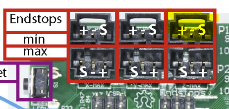
As long as you avoid plugging anything in to the ‘+’ pins (and note how they are reversed in each row), you cannot hurt anything trying out a socket and using a M119 g-code to check the endstop states. “Short out” your z-probe and send the M119. It will read ‘Triggered’ if you have the right socket.
Just realized I never followed up with a thank you.
This should get me going.
So what do you use to crimp the red connector for the plate itself? Or do you just solder it?