Igus has design wizards that allows for the calculation of wear, but the mileage of an XY is quite low compared to the wear characteristics of the rail/bearing combo
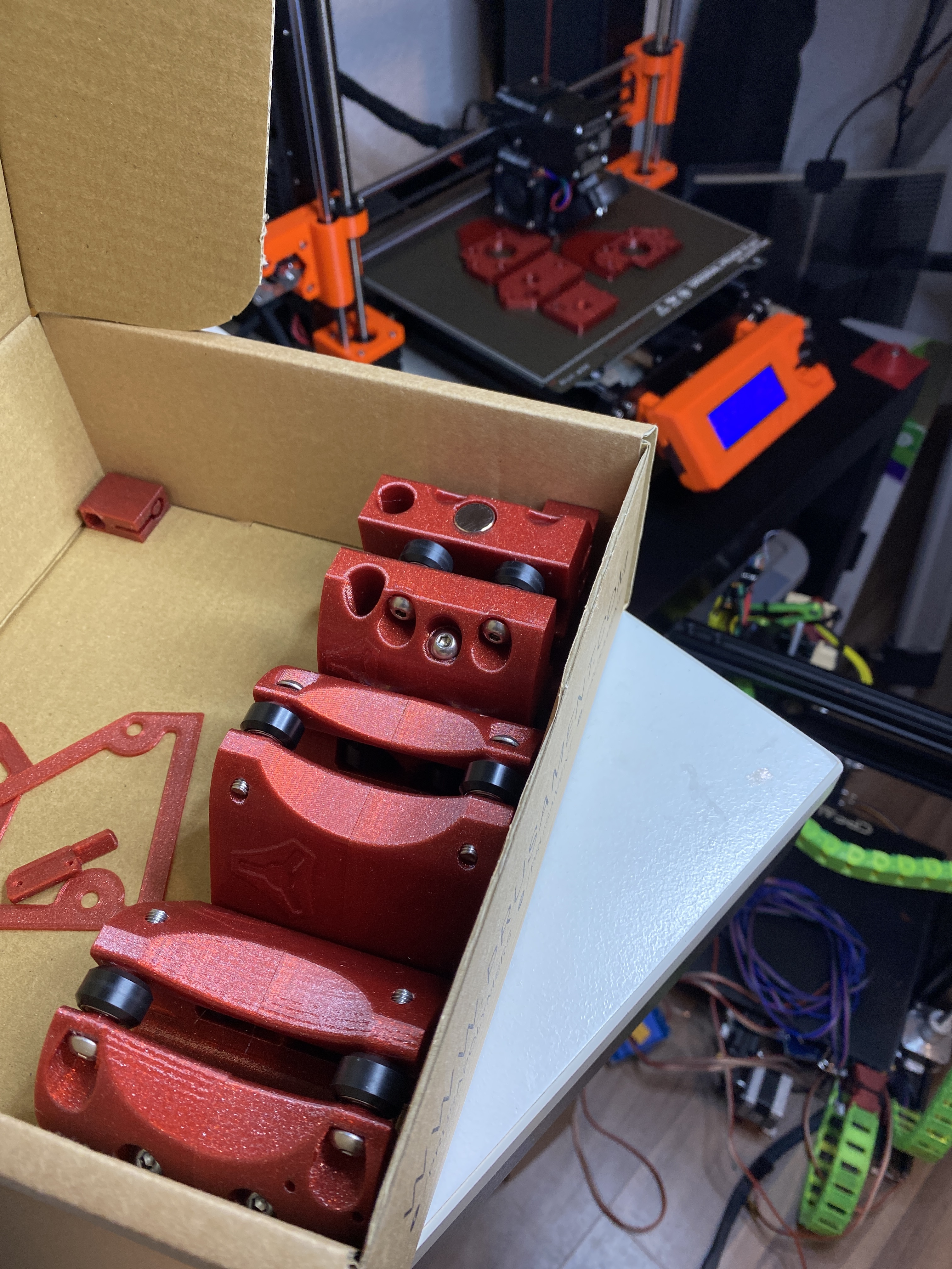
By the way, I just wanted to let everybody here know that my printer has been busy the last few days but some hours ago I started printing the first 25/18mm-parts and it’s only about 35 hours left.
The first prints are done and they fit together perfectly. Maybe a little too lose on the mid rails but i guess they don’t need to hold a lot so i could probably get them stuck real tight with one layer of adhesive tape.
So thank you @vicious1 for the files.
I’m just breeding over the calculator. Can someone help me get unstuck?
I’m going to make a similar cutout to @jeffeb3ZenXY Desk and of course I want to have maximum image area. I’m a little confused about the cutout sizing for the countertop. Maybe some can help me out?
I have a maximum space the machine and all its parts can take up beneath the countertop of 1000mm (X) and 600mm (Y) and a 10mm ball. After entering these values, the calculator puts out 2 values for each of the 2 axes for the “work area”. How big am I supposed to make the cutout? Personally I would – having tried to imagine it all very intensely in my head – go for the “actual area needed” value. But since wood countertops have this crazy property of the impossibilty of undoing wrong cuts I want to double-check before my tracksaw touches the part
P.S.: The tracksaw might just be a lie, since I’m maybe going to use a CNC router to make the cutout so I can go for a nicely fit routed recess cut for the glass pane
Yeah these should be a bit looser than the others but kinda tighten up with the hub in there as well. They should have a little drag at least when fully clamped…sound about right? They should not rattle freely.
Crud, the calc is not working for me. Shoot, I need to take a look into it. I think this dead link is causing it…hope it is just temporary, https://code.jquery.com/jquery-1.9.1.min.js
It is pretty basic though. Your footprint is 184mm larger than the sand area.
The “gotcha” here being that this assumes a point source. You have a 10mm ball, so the sandbox should be 10mm bigger than the addressable area. Basically, 87mm from the outside edges of the plastic pieces.
Amazing, thank you all. I already got my ruler, pencil and curcumscribe(?) out if the drawer and also got to the 10mm-ball special kinda figured out but it is so much better having your extra sight of eyes on this. Merci beaucoup
Monday is the day of sawing
Meanwhile the first half of the parts is assembled, while the other half is printing away.