I’ve been playing around with the G425 V command for measuring backlash with a probe on the lowrider. I seem to get on average about 0.06 to 0.12mm backlash in X and Y and 0.04 in Z. I tried changing out my mill bit with a 1/8" rod, cleaning my probe and calibration block with alcohol, tightening the belts and tightening the X carriage clamps… nothing seems to improve it.
Strangely the numbers almost always seem to either be 0.06mm off or 0.12mm off but never in between not sure why that is.
Anything else I should try before throwing in the towel and enabling backlash correction?
Are you getting 0.06 in X and 0.12 in Y consistently? Or sometimes 0.06 and sometimes 0.12 on the same axis?
I assume you always measure at same location?
I would expect that the main cause of backlash is belt stretch, in combination with the friction of the gantry. If you measure in different locations (far right vs far left on your table for example) you should see different numbers for the backlash on both sides of your 1-2-3 block.
I would be curious, if you mounted the block at a slight angle and probed along one edge, if the probe location is a perfect line or if it is slightly ‘lumpy’.
In other words, probe against the side of the block (say +X direction), then M114, then step Y by +1 mm, and repeat, probe in +X direction, M114, and step Y by +1mm, and record the locations. If you had a pulley that were slightly eccentric for example then you might see a periodic behavior superimposed on the ideal linear trace. If that is large then you might not actually have backlash and instead you have the appearance of backlash when the issue is something else.
Another experiment that might be interesting: set up a dial indicator on the side of your gantry. Then press on the gantry in one direction and gently release. Record the dial indicator position. Then push it the other way and release. See if the dial indicator position is different. This essentially the same as backlash measurement but nothing is moving except the friction and stiffness operating similar to the manner that creates backlash.
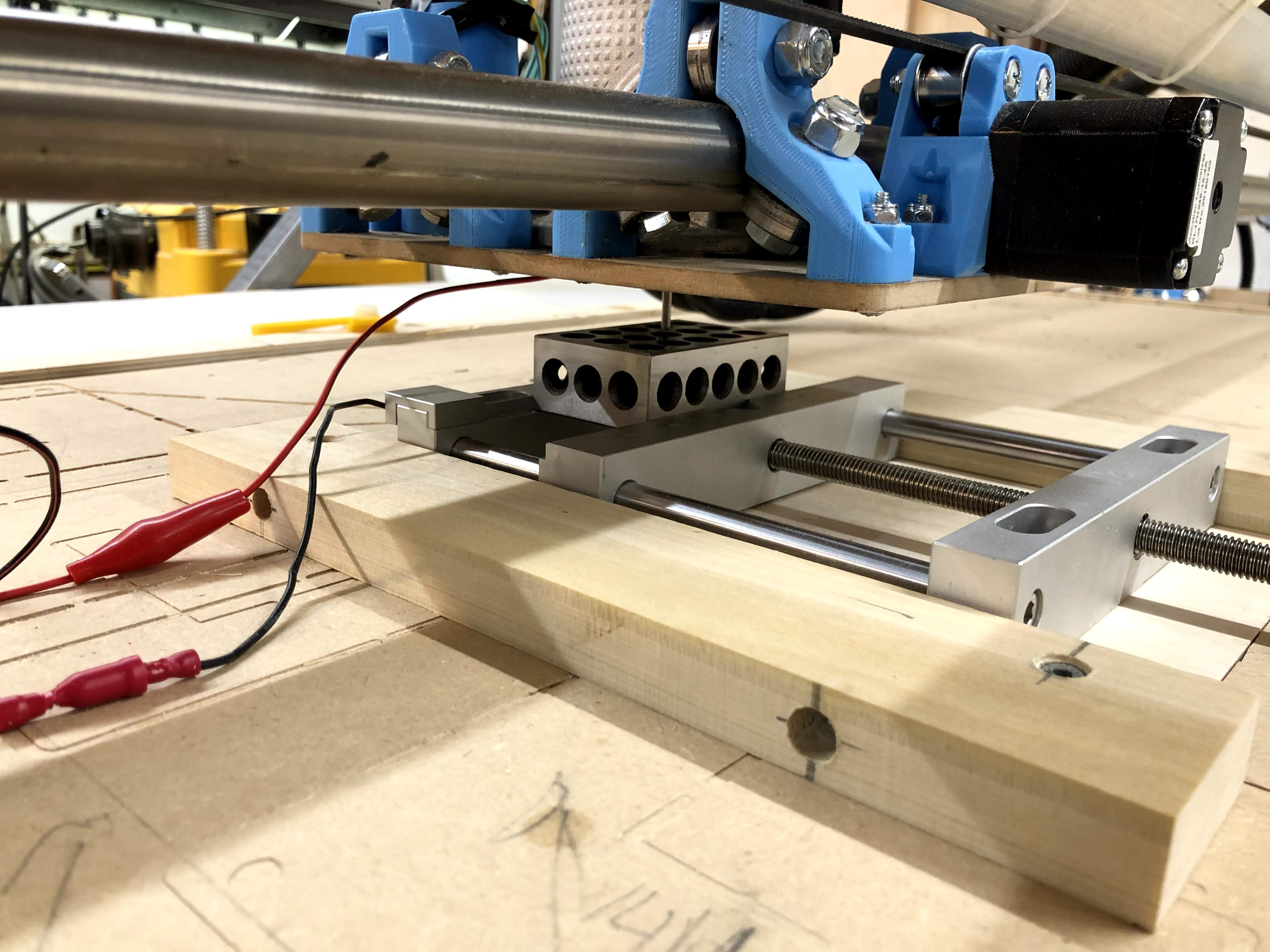
I also have a 1-2-3 block as shown in the picture. I do have a relatively cheap one from AliExpress, but the edges of my block are chamfered very inaccurately. The faces are very flat and straight and square and everything, but the edges are very imprecise. So tilting the block would not give you a very nice straight line.
If you happen to have feeler gauges, or a good straight edge, I’d use that.
I did this a while ago on my MPCNC. I typically got a 0.05mm difference! And I only measured 0.02mm backlash using probing.
When pulling on the end mill, you also put load on the center assembly. With probing, there is no load at all. I’d expect the lowrider to have a stiffer center assembly, so maybe the two kinds of measurements will be much closer.
When you’re actually cutting things, you also get load on the center assembly of course. So the real world backlash may be larger than what you measure with probing, and using a dial indicator may be more realistic.
Sorry I was not clear. What I meant was rotating the block around the Z axis, and probing one face. At an angle, probing in the X direction at successive Y positions would produce gradually increasing (or decreasing) X positions. If the motion in X were irregular then this could show up as X irregularities across regular Y movements. By probing from one side the backlash is not part of the equation. A straight edge would also work.
Blockquote
Are you getting 0.06 in X and 0.12 in Y consistently? Or sometimes 0.06 and sometimes 0.12 on the same axis?
It’s not consistent… sometimes 0.06 and sometimes 0.12 on any of right and left and front and back. Yes I am always measuring at the same location. I tightened the belts quite a lot and it didn’t seem to have any effect.
You can also calculate the backlash with the G38.2 and G38.4 probe commands. That would give you full control over the speed and probe location. You do need to enable it in the firmware (search for G38 in the Configuration_adv.h file if you haven’t done so yet).
I was just looking around in the source code for G425. First it moves until the probe touches, then it moves away slowly until contact breaks, and then it moves to the next position with a different (faster) feedrate. Probing moves use the CALIBRATION_FEEDRATE_SLOW feedrate.
When probing, it moves in discrete steps of CALIBRATION_MEASUREMENT_RESOLUTION millimeters. You might want to double check whether you’ve set this to a very small value. The default is 0.01. If you’ve set this to 0.06 then you’ve found your problem!
If you’ve set this to 0.06 then you’ve found your problem!
Yep I thought of that… mine is still at the default 0.01
Funny thing is, the movement probing towards the block is much slower than the movement probing away. I never configured the G38.4 commands though maybe that’s causing problems there.
The movement probing away is tiny, so you probably can’t even see the actual probing (moving until contact breaks). After probing is done, it moves away with a faster feedrate.
1.Enabling G38.4 and testing manually… I get 0.01mm backlash in X and Y (!)
2.Enabling microstepping… machine went crazy couldn’t get it to work.
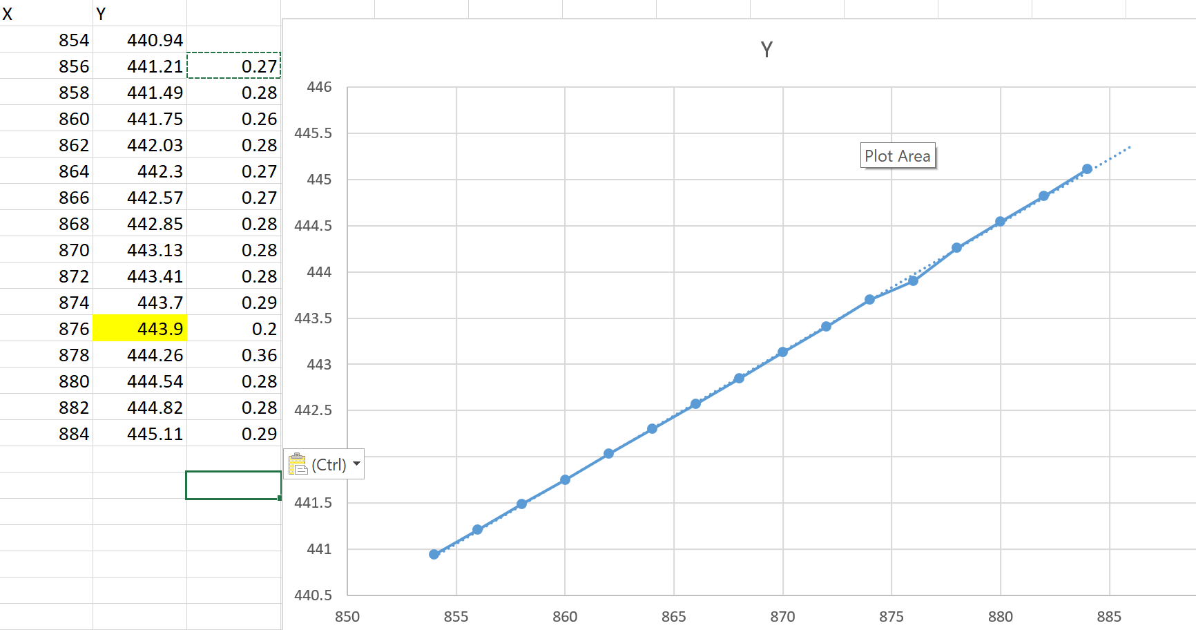
3.Setting up a straight edge at an angle and probing… I did get one reading that was off but the rest look OK (graph attached). I’m thinking maybe I made an error transcribing a number or I would have seen it repeat or at least not show up so consistently in G425.
So I’m just as confused.
Things I can think of that are going on:
G425 is just wrong because of a bug or it is doing some weird calculation based on a cone shaped printer nozzle and the exact width of the block your are probing.
G425 is right and some combination of movements when it travels around the block is causing the probe values to be off.
Tried cleaning the bearings and switched back to my mill from the rod… same results.
Then I tried manually probing, flying the carriage all around with the joystick on all axis, and returning to the same position and probing. 0.02mm difference.
I think I figured out where the number is coming from though… I tried probing left, right, front and back of my block. When I subtract the left and right sides and then subtract the width of my probe I wind up with the block probing as 0.14mm smaller than it should be. When I re-probed the left and right sides I got almost the exact same size measurement again.
So is my solution simply to adjust my steps per mm ?? I don’t think I ever calibrated my machine for size.
I don’t think the steps per mm can explain the backlash measurements you get with G425. As far as I can tell from the source code, G425 is kind of the same as G38.2 followed by G38.4 in the opposite direction. Except that the implementation is different. G425 moves in discrete steps and checks the probe between each of those steps. G38 starts moving and stops as soon as the probe is opened or closed, exactly like homing does.
It’s very easy to verify whether G38 works. Just check the end stop state with M119 after every command to see if it’s what you expect. So if you get 0.01 or 0.02mm with this method, I’m sure it’s correct.
I guess so. For the most accurate results, you also need to make sure that your block is not tilted or rotated I think. You can do this by probing several points along each face and plot the lines like you did in the Excel above. The lines should be perfectly horizontal or vertical. If you achieve that, you also know that your vise is plumb. (If you don’t have perfectly horizontal or vertical lines, a little extra math will tell you the exact measured dimensions of your object.)