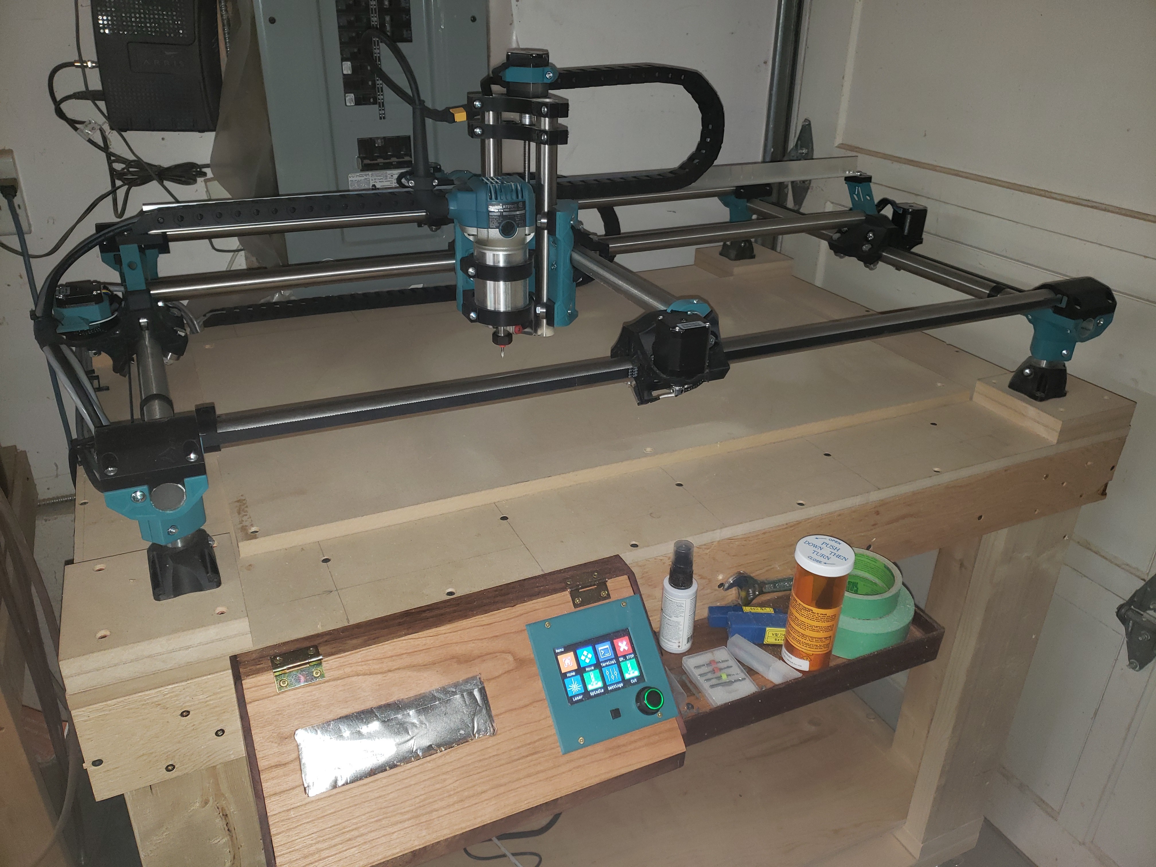
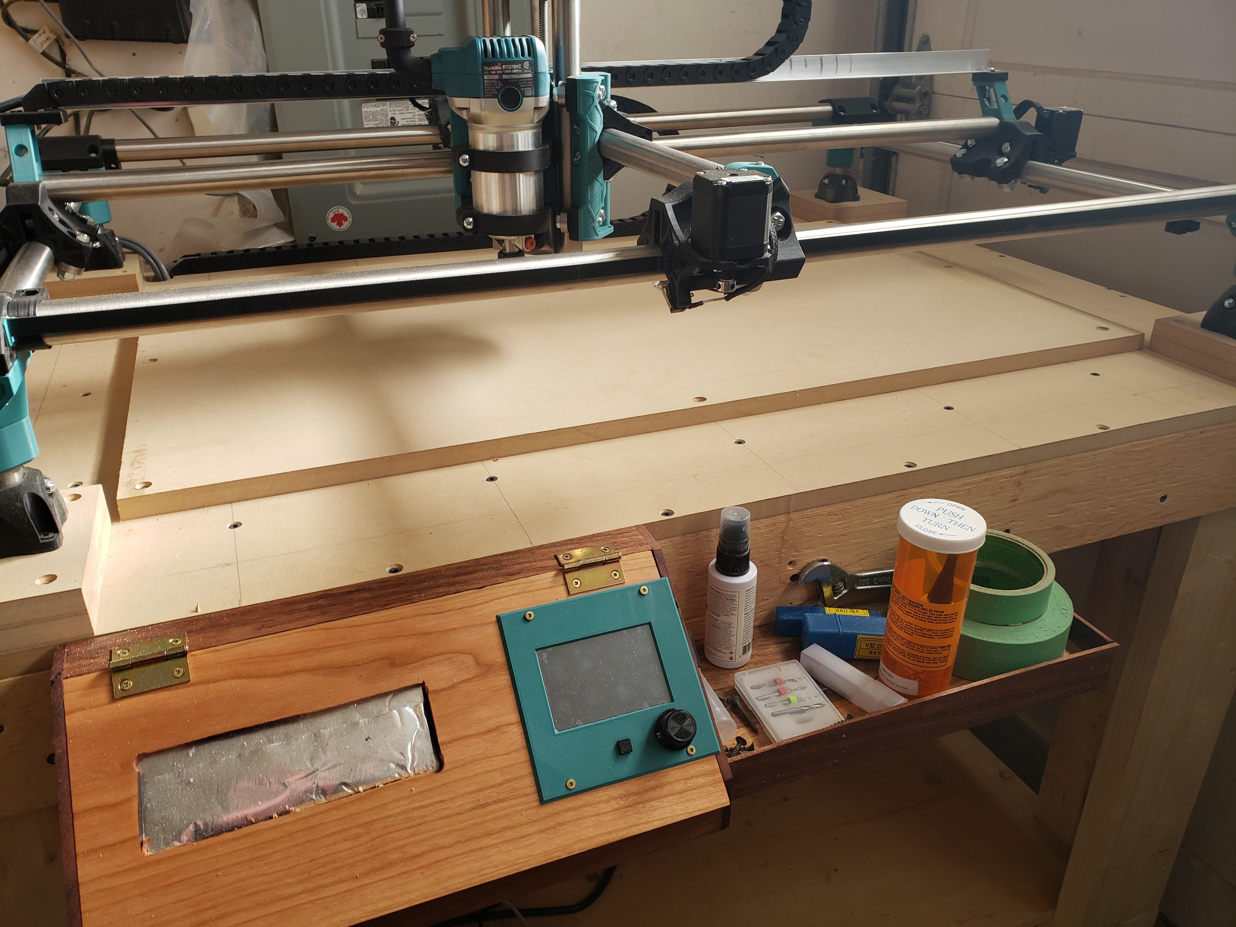
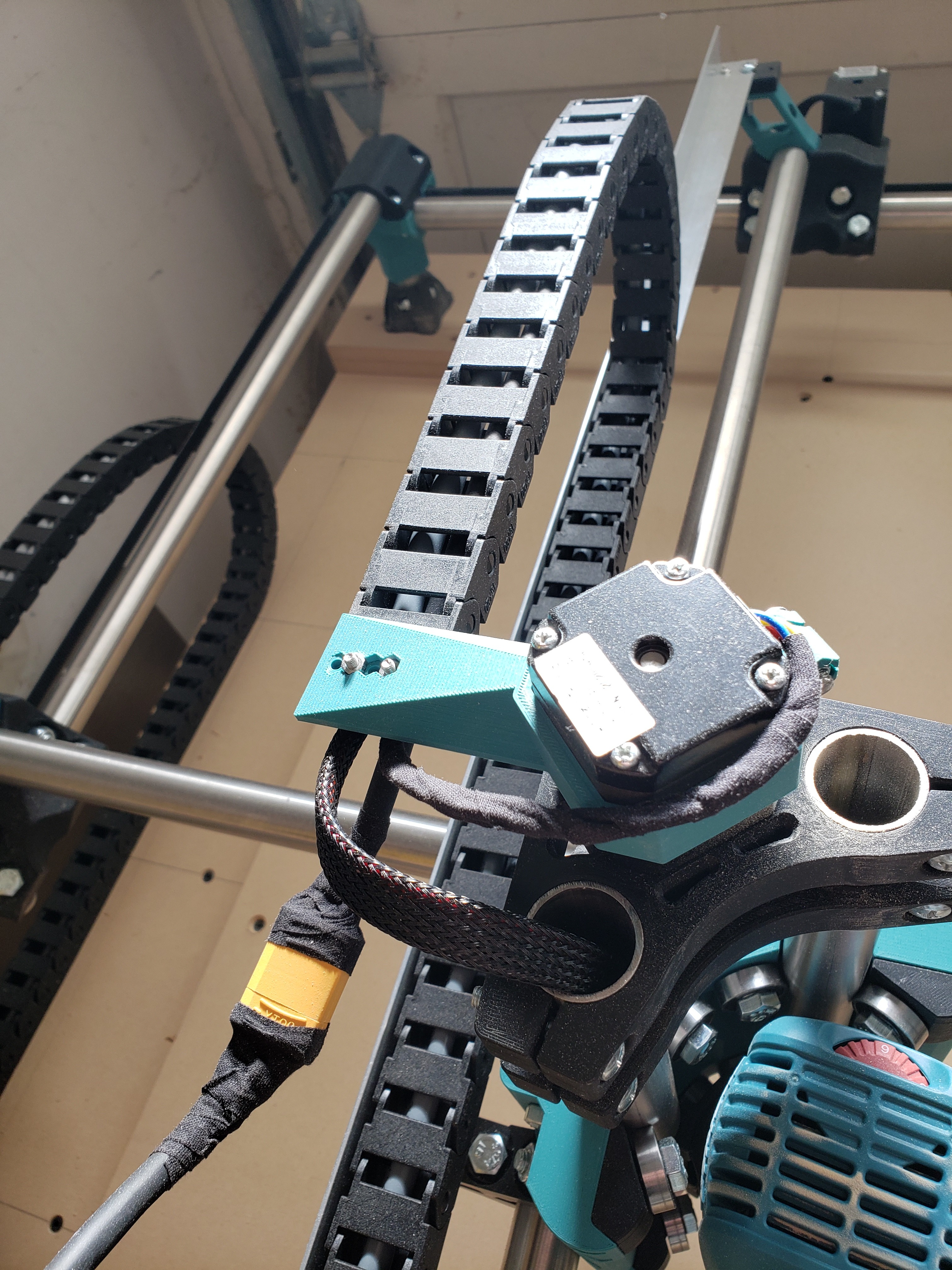
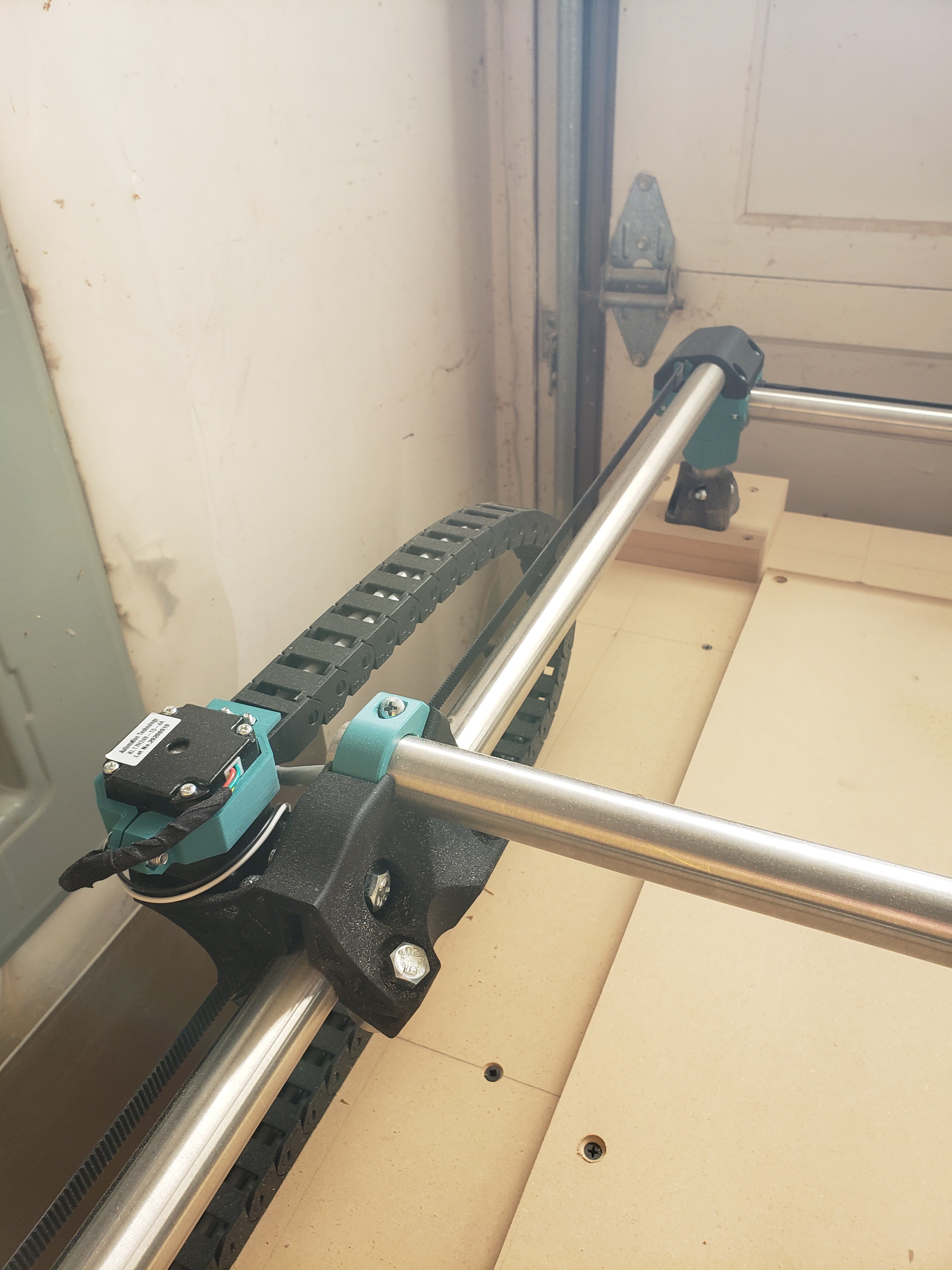
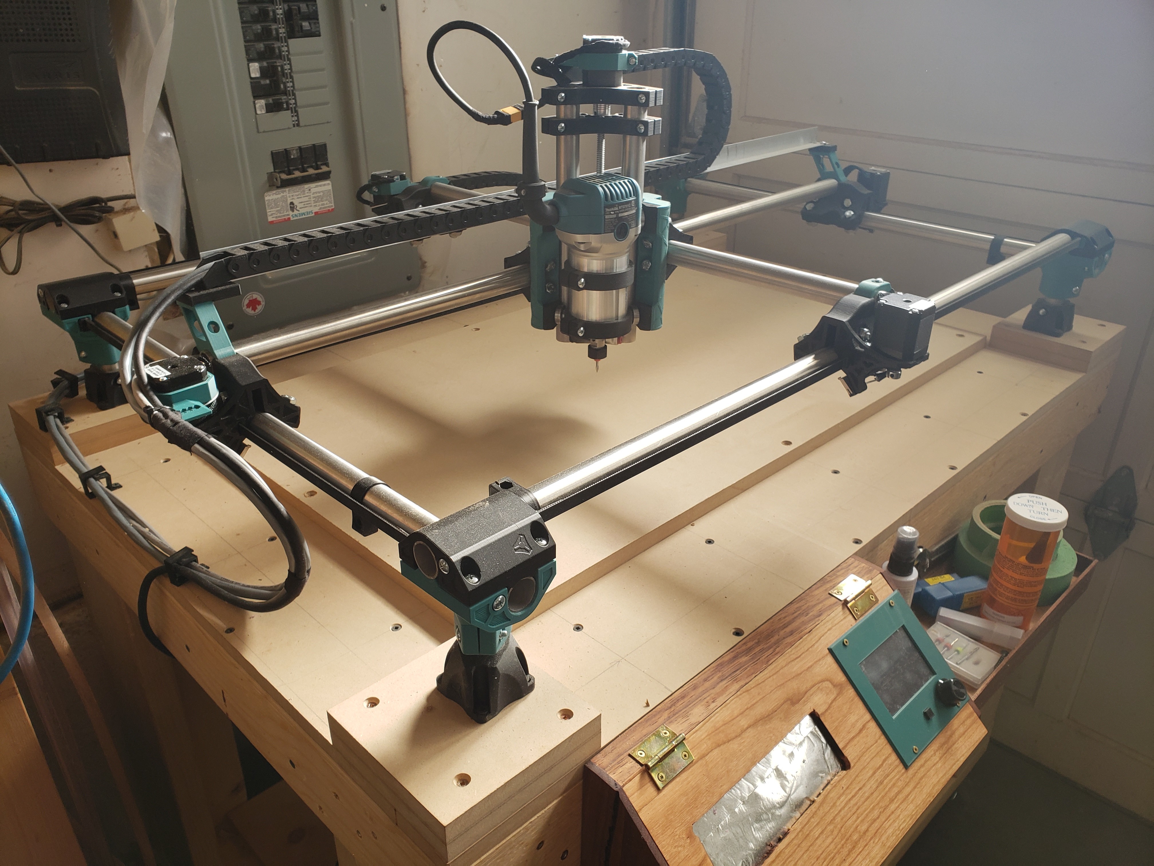
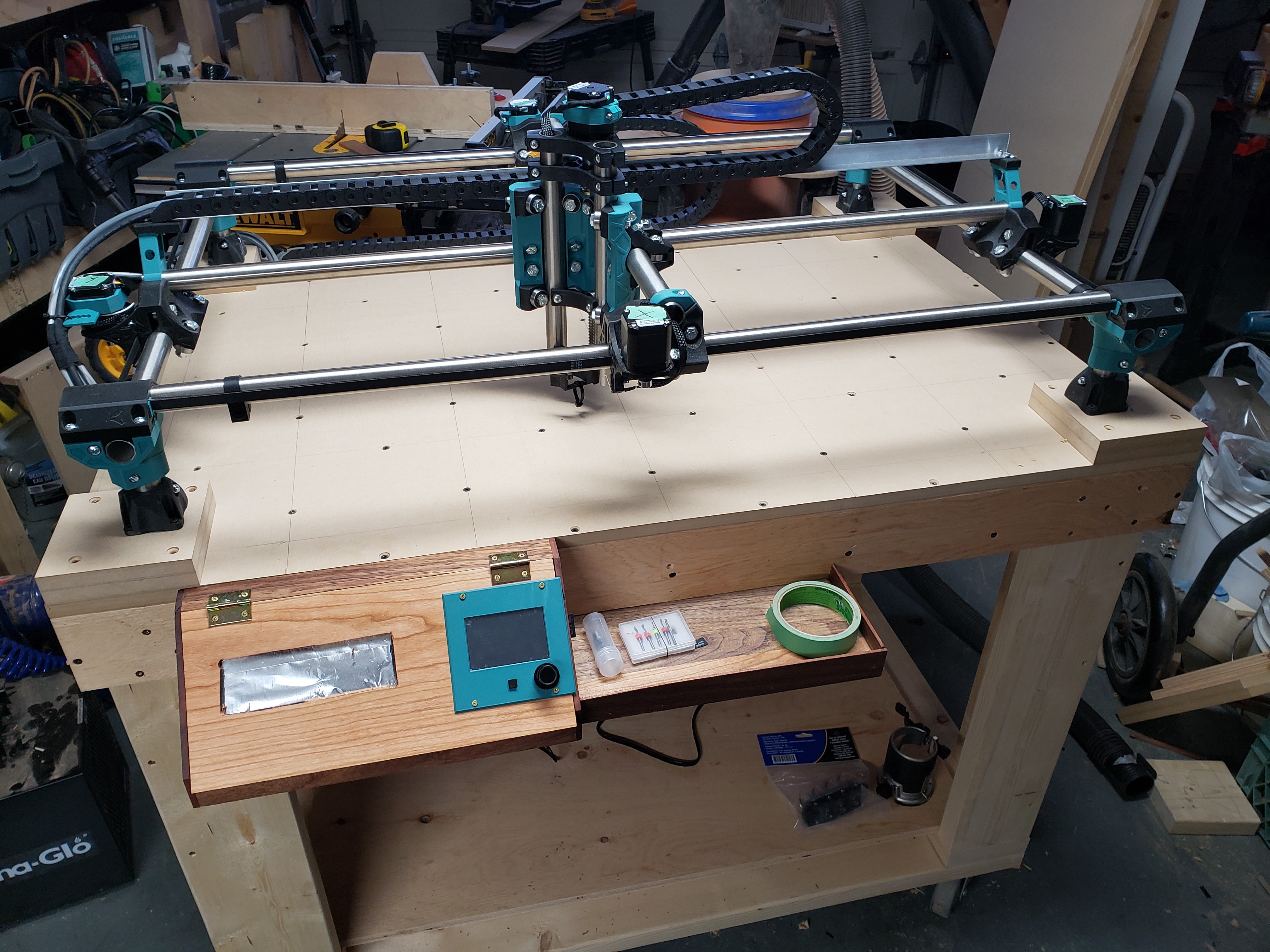
I finished most my wire management. Added a few drag chains. Made up a quick control box with scrap wood. Almost ready to add my spindle!
Oh and I decided to order a laser…that will be fun.
Here is the laser I have coming.
I finished most my wire management. Added a few drag chains. Made up a quick control box with scrap wood. Almost ready to add my spindle!
Oh and I decided to order a laser…that will be fun.
Here is the laser I have coming.
WRT your laser: given all the overblown specs I see on lasers, I thought their statement “This is the most powerful visible light laser diode currently available” was hype. But after reading about the NUBM44 diode, maybe this one lives up its specs. I’m curious to know what signal voltages it will accept. This is something you will need to know, so hopefully it will be in the documentation when you receive the laser.
To be honest, im still learning but I have heard good things about this laser. As far as the voltage it accepts, i think this is supplied by the Constant current driver which is included. Either way, im sure ill figure it out when it arrives.
I’m referring to the voltage of the signal line from the control board. Some lasers require a specific voltage like 3.3V, 5V, or 12V. Others will accept a range of voltages. You will have the easiest time setting it up if it accepts 5V. I’m assuming from the labeling on the box in your picture, you purchased a SKR Pro board. Laser support is already enabled in the V1 maintained firmware for this board, and a 5V pin is assigned for the laser in the firmware.
Yes I have the SKR Pro, Fingers crossed the signal will accept 5v. Ill ask one of the guys i know is using this laser.
So apparently the laser signal voltage will work with either 3.3 or 5v and will work just fine with my SKR Pro. So that’s good news.
Did my first cuts in mdf today. Pretty happy with its results. Gonna work at learning estlcam over the next while.
Very nice first cuts. I just took a look at V509D of the MPCNC firmware. Your laser pins are defined in the top of configuration.h:
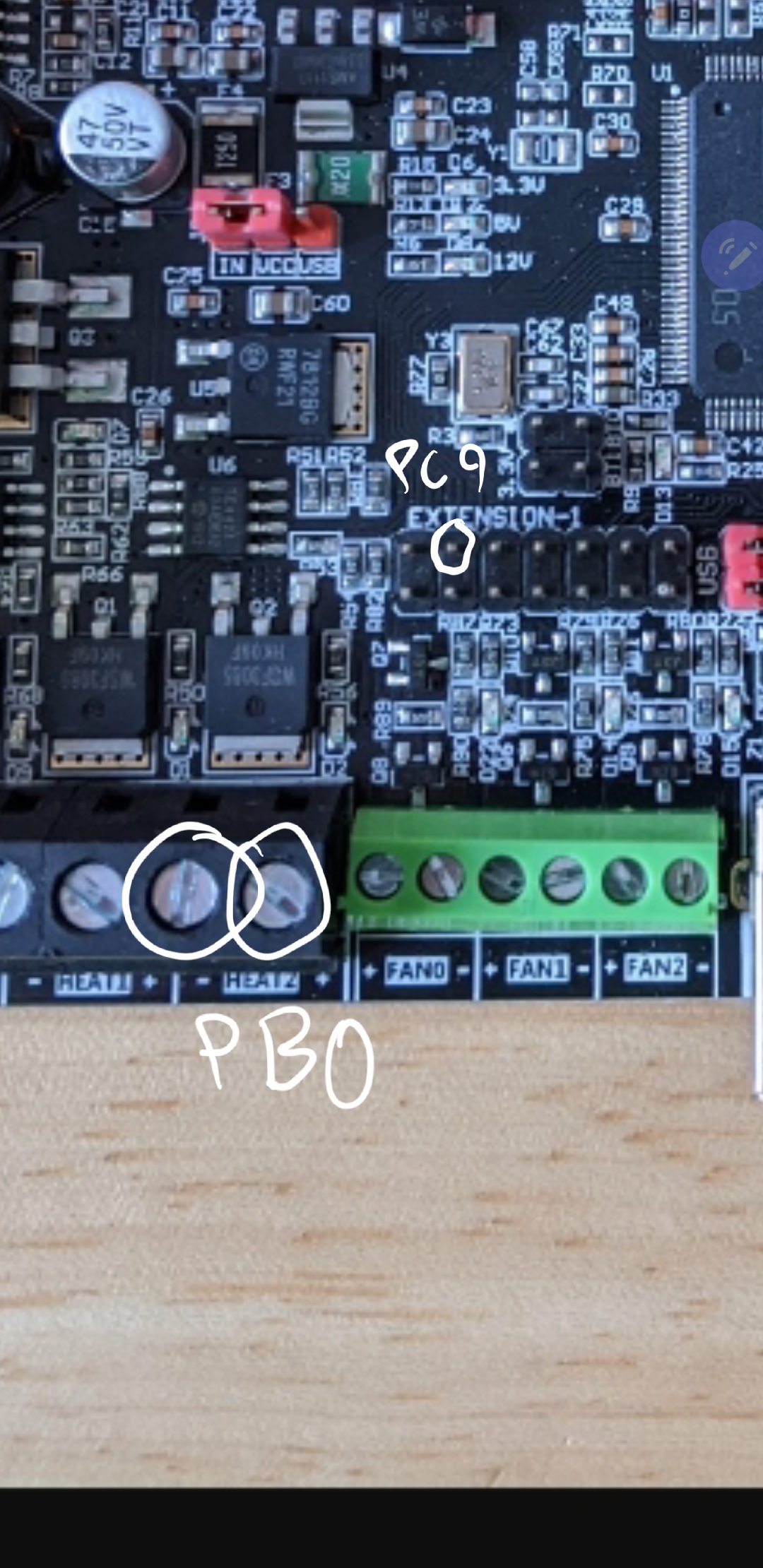
#define SPINDLE_LASER_PWM_PIN PC9
#define SPINDLE_LASER_ENA_PIN PB0 // Heater2
Pin PC9 is located on Extension 1.
When you get it up and running, I’d be curious to know whether this laser lives up to its “most powerful visible light laser currently available” label.
Thanks for checking that out! I’ll keep things updated on here as I progress.
This is what another user said about this laser.
“It’s outstanding! Truly a beast. The fan is a bit obnoxious in the ways of sound. But the laser is great.
Customer service is very good. Communication is also very good. Worth every penny and I’ve put about 250 hours on mine already and I’ve owned it for about 3 months.”
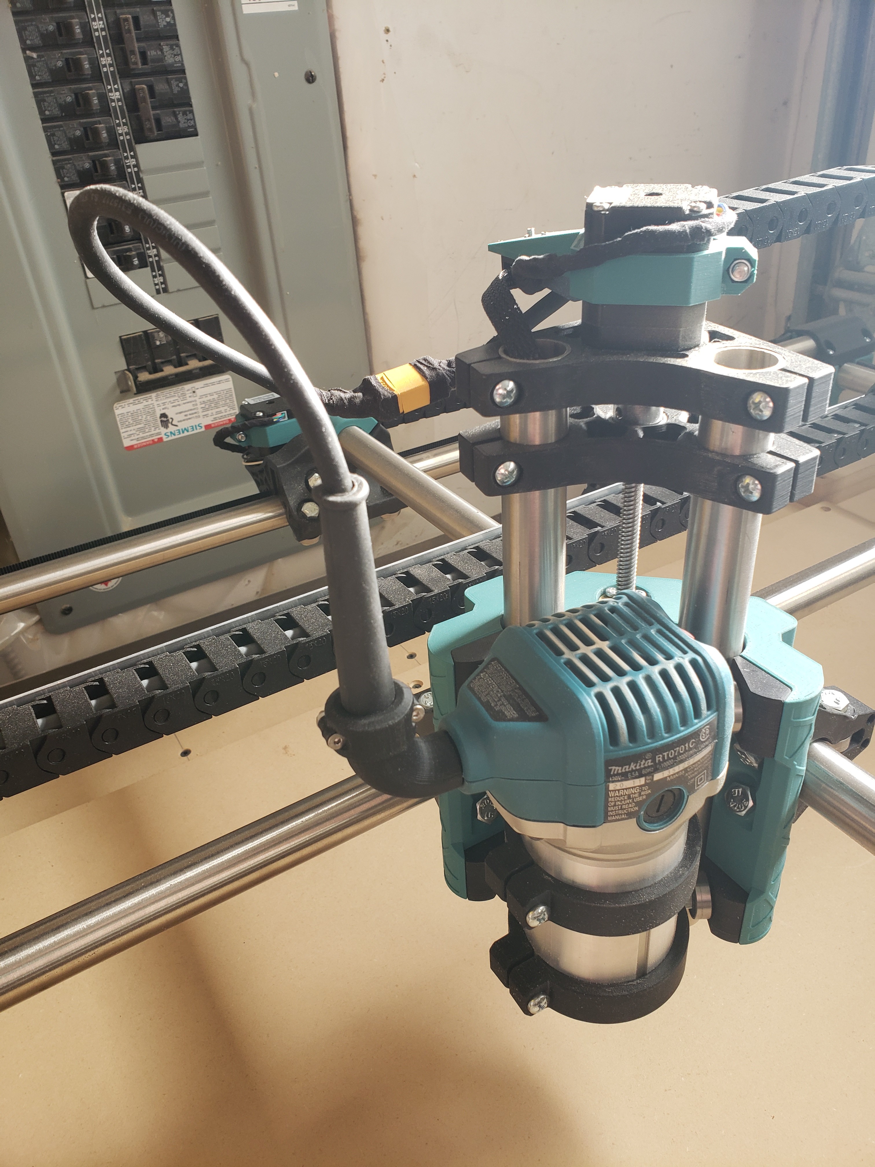
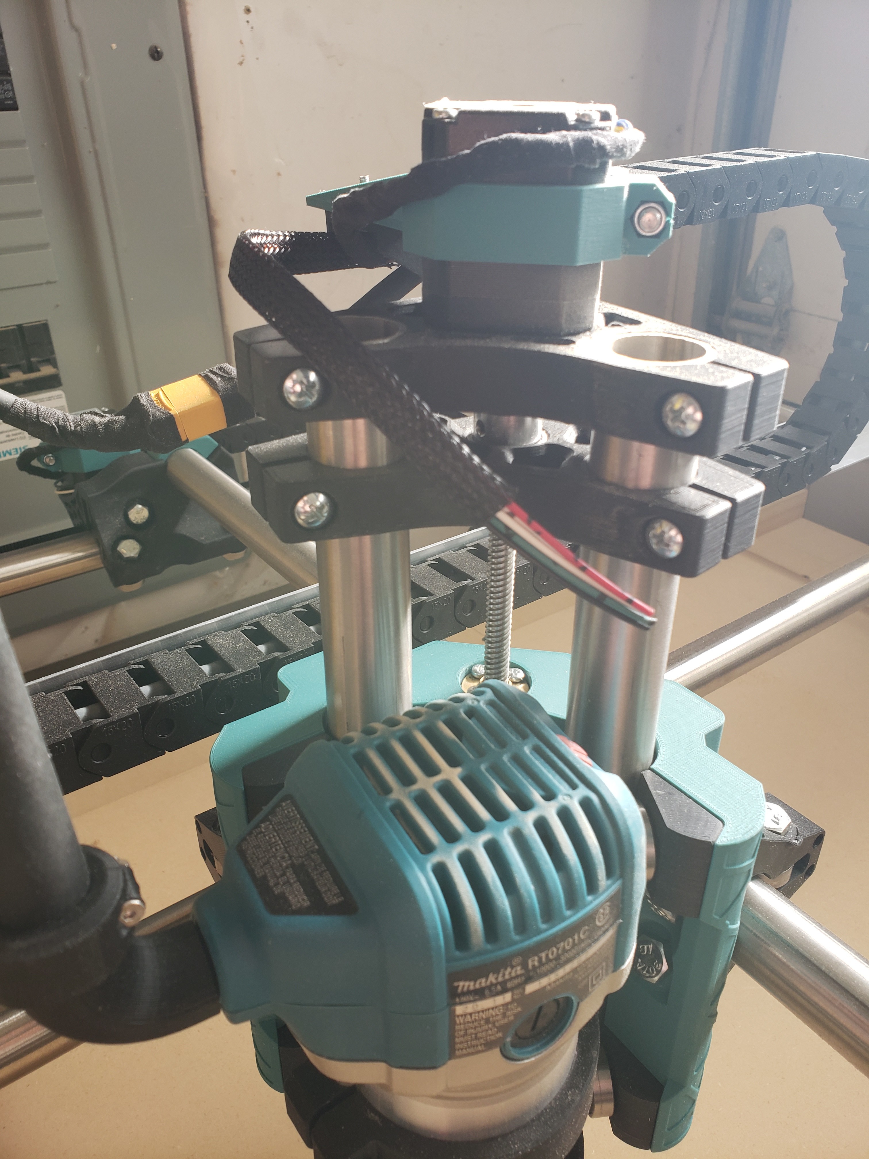
Can you post some pictures of your rig please. Do you swap laser and spindle?
sure, ill post more pictures in a bit. Laser is still on order, and I havent yet figured out how to mount. I think I will design a mount that can fit inside my spindle mount. that way it would only take a minute to swap between spindle and laser.
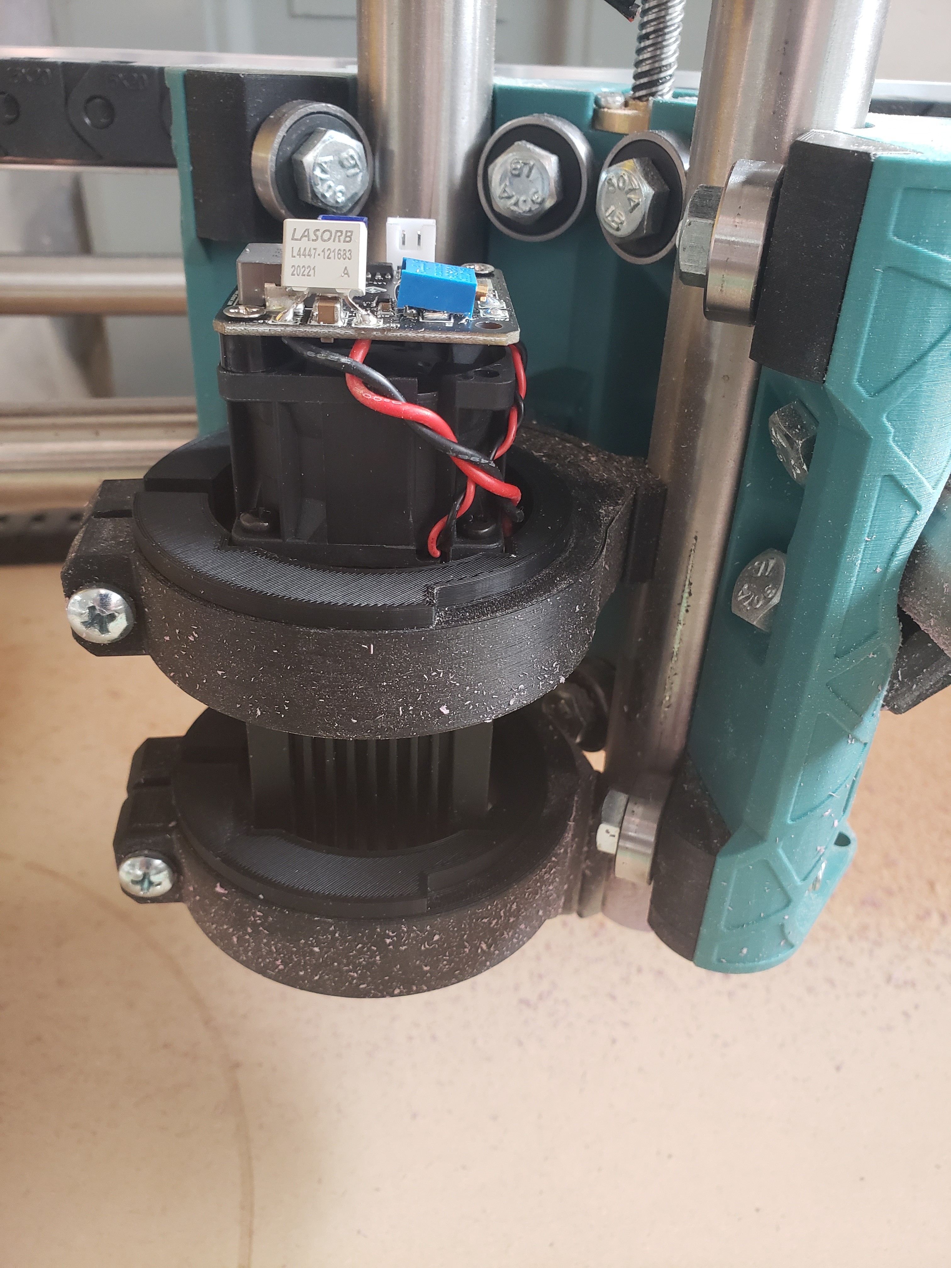
I got my laser and trying to wire it up. When I check the voltage across PC9 and PB0, should I use + or - on PB0?
Either way neither pin gives me 5v, I get closer to 12v. My laser needs 3.3 or 5v. Any idea where the 5v pin is that is for laser signal?
I don’t have a laser. Are you sure you need an enable pin? Though the pins definition have one, I’ve not seen any of the lasers that come across this forum using one (though I haven’t tracked the issue closely). Usually I just see them use the PWM pin. So your laser would get PC9 and a ground wire of some sort to active your laser. I’m pretty sure that PC9 is a 5V PWM pin.
If you need a 5V enable pin as well as the PWM pin, you will need to set the SPINDLE_LASER_ENA_PIN to an unused 5V pin (doesn’t have to be PWM). I’m not sure what pins are being used. You can research the issue by looking in this file:
pins/stm32f4/pins_BTT_SKR_PRO_V1_2.h
Hey Robert,
Your probably right, Im pretty sure I dont need an enable pin but ill double check…wasnt reading it properly, i just thought the two mentioned pins would have been the two signal wires from my laser.
Ill try PC9 and a ground pin then. it should show 5v with a voltmeter if it is correct i believe? that would make more sense, Thanks. ill update here
You should not see any voltage on the PC9 pin until you send an M3 or M4 command. After sending an M3 with no parameters, you should see 5V on the pin. PWM values are from 0 to 255, so according to the reference, if you send:
M3 O128
It should be half power and you should see something like (give or take) 2.5V on your meter.
If you are using your display to turn the the laser on and off and you are not getting a result, you might try sending the g-codes directly using an SD card or Repetier-Host.
Ok. That may make sense why I wasn’t seeing voltage then.
So I tried to plug the laser in and it went full power right away. Screen said the laser was off…hmm
Definitely a powerful laser! Started burning my spoilboard instantly.
You were correct. I checked voltage after entering m3 0128 and it was 2.6, so that working…just need to figure out why my laser is going full power.
Ok now I am able to power on the laser without it firing. The laser section of the display does not seem to work for the laser but when I input M03 123 the laser does turn on.
I put a gcode in, but for some reason with this gcode the laser only does a very quick pulse. When I reviewed the gcode it seemed ok to me? Section of the code posted below. Seems like M03 S102 should turn on the laser but not sure why its just a quick pulse,
LightBurn 0.9.21
; Marlin device profile, absolute coords
; Bounds: X6.06 Y2.16 to X140.18 Y62.32
G21
G90
; Cut @ 28 mm/sec, 40% power
M9
M05
G0X25.94 Y21.15 F0
; Layer C00
M03 S102
G1X25.92 F1680
G1X25.91 Y21.17
G1X25.89 Y21.18
G1X25.88 Y21.2
G1X25.87 Y21.21
G1X25.86 Y21.22
G1X25.85 Y21.24
G1X25.81 Y21.35
G1X25.76 Y21.54
G1X25.7 Y21.74
…