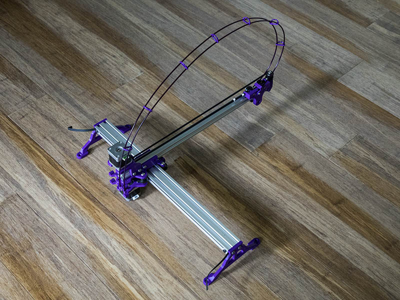
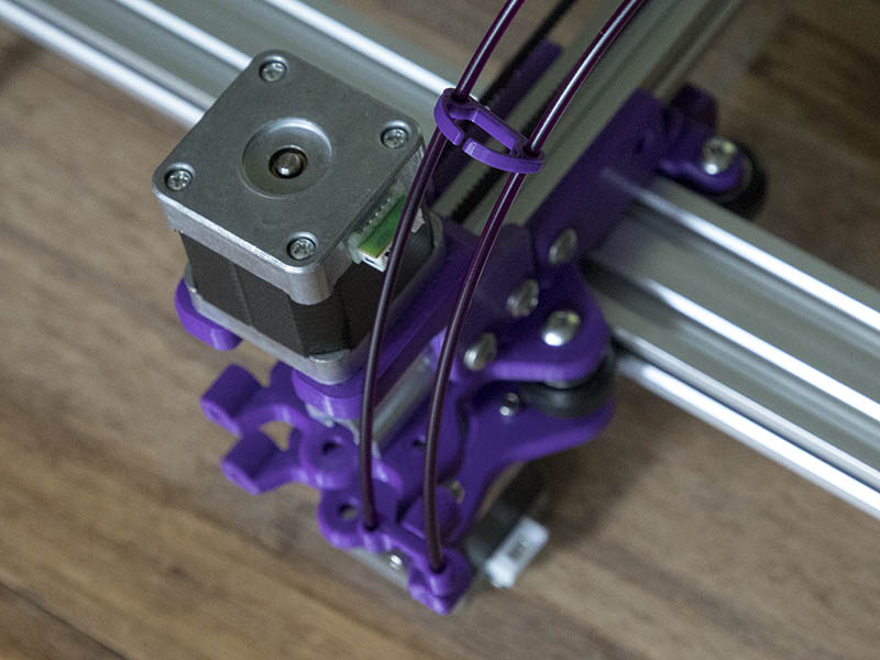
I decided to try Ivan Miranda’s idea for a simple cable chain today for the laser wires. He uses this on his giant 3d printer build. This uses 3mm Filament & I had some samples laying around. I used 3 feet lengths & made mine quite a bit smaller between the original design since there are probably only 3 wires going thru it. It has a tendency to rotate wonky when moving it. I just made a couple of simple brackets for the back & carriage mount to test it. The filament lengths do need to be shorter, so will shorten 3-6" at a time & add some more Filament Clip SPACERS. It is certainly light weight.
I didn’t notice before, but he has 3rd tube of some sort spanning between all the clips. Maybe it is that PTFE Capricornus tubing. Here is the video at that time spot. I could not file a STL file for those filament clips.
I had some PTFE Capricornus tubing & tried that in the center of those 2 filament hoops & it was not any better, so giving up on that idea. I fine tuned some of the parts today. For all the T-nut holes, I added another .5mm as 6mm still seems to hit the inside extrusion with a M5x12mm screw. The bottom M5x10 screws that connect underneath the 2020, I changed the countersink from 2.0mm to 1.5mm. I have not reprinted these parts yet.
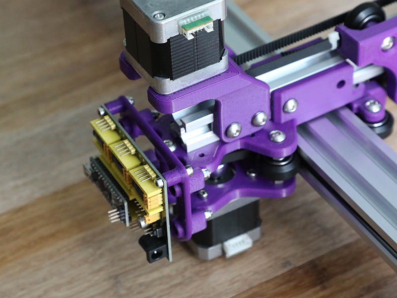
I designed & printed a back electronics mount for the Keystudio CNC V4 board. After test fitting that, I also shortened the depth of the M3 holes in the Upper & lower plate so M3x16mm screws would work well. Now that I think about it that back mounting part is still 9.75mm thick where the M3 holes are. I may as well shorten it another 4mm to use M3x12mm screws. 5.75mm should be plenty thick.
After I get all these changes done & reprinted, I plan to upload the design to thingiverse & give a link to this thread & Mike’s build log thread. That is if Mike does not object to that.
No objections here. It is good that you are going to release your design to thingverse…giving back and all that… and congrats on ending up with a working machine you are happy with.
I must say I wasn’t keen on the cable management idea, I thought it detracted from the clean lines of the simple design and it doesn’t really need cable management anyway, (unless built with a really long arm) I found just attaching the cable half way along the arm with the wires pointing upwards was sufficient to keep the remainder out of the way and if a bit more support was needed I was going to add a 0.5x2mm carbon strip to the wires.
Thanks for your support. Those wires were also going to add height to the design which would make the cover taller, but was an interesting idea to explore. Being just 3 wires, it should not be much of a bother. The motors I ordered come with 30cm length cables which should be a good length for this design. Will probably only need to wire tie one loop.
I was actually thinking about that yesterday as I had seen that before in these forums, but forgot about it before researching for the source. This looks like the thread you are referring to: Better than a cable chain?
Since it will be at least a month before getting the laser, I might piddle with that idea. Thanks for bringing it to my attention again.
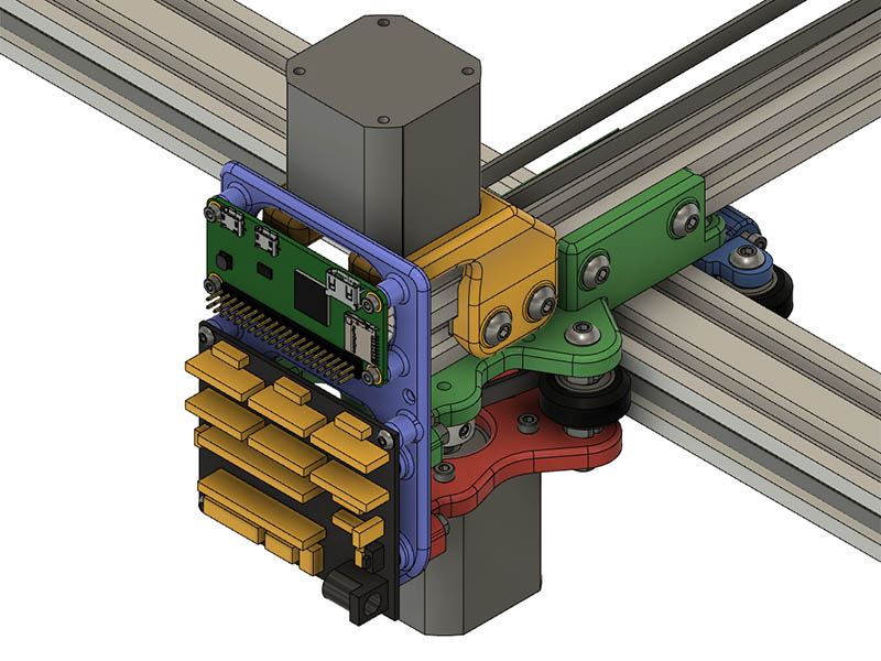
I changed the back electronics mount to allow for the Raspberry Pi Zero W. I had to move the mounting brackets on the top & lower mount back some to clear the motor above. I am using 16mm length screws for all the electronics board holes. I added a couple of holes on the sides of the board to attach wire ties to. I could not find a model of the keystudio board, so just pulled dimensions from the board to draw a simple version of it.
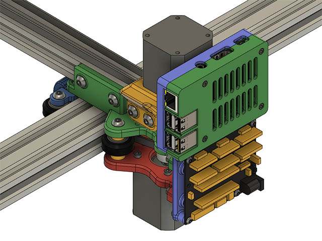
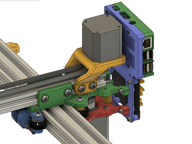
Since I will probably end up using a regular pi 3B+ with this I made a case similar to what I have on my Rolling Plotter design. I will also add a simple plate cover to the other board eventually.
I flashed the firmware on the nano board attached to the keyestudio board today & had a little problem until I found this video. Looks like my main problem was selecting “ATmega328P (Old Bootloader)” instead of just “ATmega328P” that I did initially. She changed 6 pins in the cpu_map.h file also. Do these need to be changed for my situation? #define X_STEP_BIT 5 // Uno Digital Pin 2 #define Y_STEP_BIT 6 // Uno Digital Pin 3 #define Z_STEP_BIT 7 // Uno Digital Pin 4
#define X_DIRECTION_BIT 2 // Uno Digital Pin 5 #define Y_DIRECTION_BIT 3 // Uno Digital Pin 6 #define Z_DIRECTION_BIT 4 // Uno Digital Pin 7
I’ve sometimes/usually had to select the “old bootloader” option to flash the Nano… but that shouldn’t do anything to Grbl’s configuration. I’m flashing Grbl 1.1h onto everything nowadays… and never had to dig into the configuration file.
EDIT: I think that particular V4 board has the step and direction swapped (necessitating the pin swap they did) and, now that I think about it, I did run into that board in the very earliest stages of my “Inexpensive LinuxCNC Interface” efforts. But IIRC it also had the micro-stepping jumpers messed up as well. So I declared that board “NOT Grbl-compatible”, ditched it, and picked up another board out of my stash that was compatible. I summarized the problems I found with that board here. Here was my verdict after Googling that board and seeing other folks were finding the same issues…
" … If you Google “contr01 by grbl” or “nano+a4988 cnc” or “cnc shield v4” you will see the “rumblings” I spoke of… numerous folks have had issues with these boards. But with equally common/cheap, known-good, CNC shields readily available it really doesn’t make sense IMHO to spend the time fixing this one… i.e. it’s no great loss."
Thanks, I will undo those changes to cpu_map.h file to start with & change them if it is a problem. I will have to find some spare nema 17’s around here as the motors I ordered from aliexpress were canceled for some reason. The motors I have on my test assembly are actually bad, but think I have a couple of good one’s around here somewhere.
Dave, after watching that video… did you notice the “growl” and rough sounds that little CNC machine was making? Pretty sure that was because the micro-stepping jumpers are mis-wired and non-functional, leaving the drivers permanently fixed in 1:1 single-step mode. I found my post, with pictures and more detail about the issues with that board. It is simply mis-wired and NOT Grbl compatible… and IMO not worth messing with. There are many other, similar, boards out there that ARE compatible and you don’t have to mess with Grbl’s configuration.
Found this Instructable by someone who went through all the antics to “fix” this board. Still, having to swap the “standard” Grbl mapping for step and direction pins makes this board NON-Grbl-compatible and therefore “broken” IMHO.
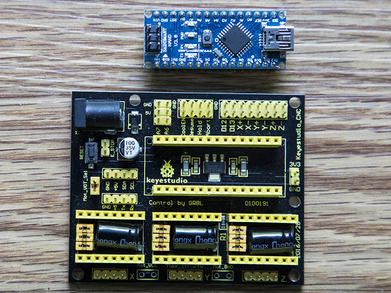
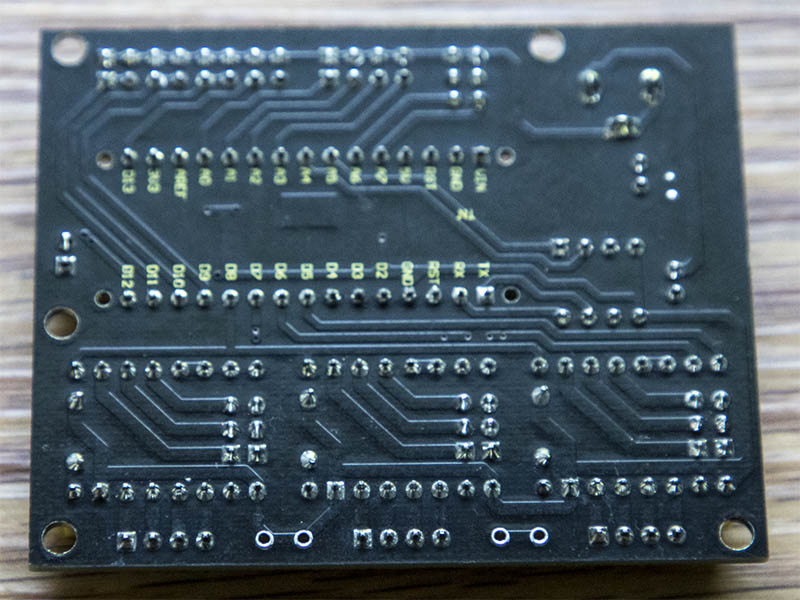
Are those clones of the keyestudio board? I have the keyestudio board & comparing the tracings on the back of the board, they do not look the same as the one in that instructable. Until I hook the motors up, will probably not know for sure if there is a problem with it or not. I don’t mind getting a better board if I need to, but would like to see if this one works first. Here are photos of the board I have. I plan to use DRV8825 drivers.
The Keyestudio boards work fine… I’ve used them numerous times. They are indeed Grbl-compatible and require no changes to the Grbl configuration file. I was just trying to warn you NOT to make the changes in that video… THEY were using a broken board.
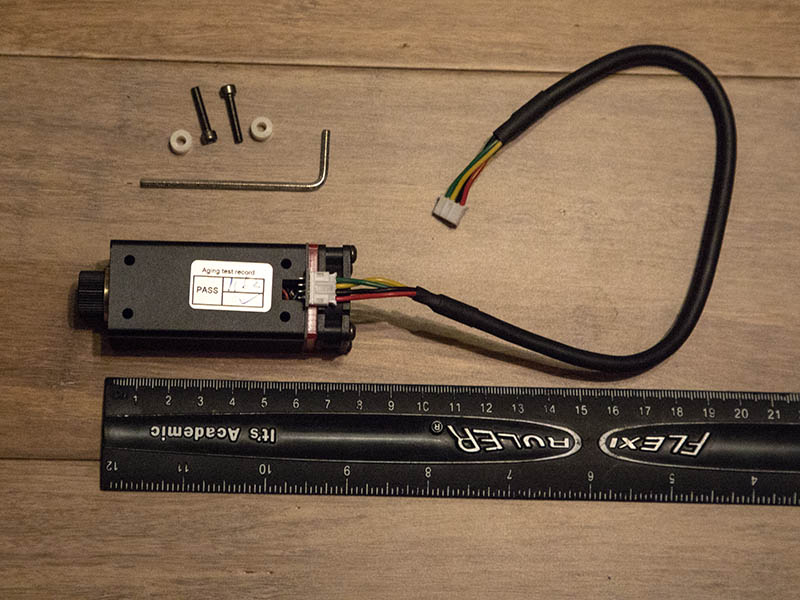
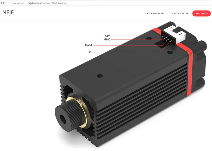
I received my two 6W lasers yesterday & need some help with the wiring. It only took 2.5 weeks to get here from China. I still have to wait for the 3.3v-5v shifters & safety glasses before testing it, but in the meanwhile thought I would see if I can get the wiring straight before then. The color coding on the wire they sent would lead me to think their webpage is wrong, but they might not follow standard wiring colors of red for + & black for ground. My wife pointed out something about the Chinese that I had not heard before which might be why somethings are backwards to us. Traditional Chinese text is read in columns Vertically from Right to Left. Here is the Wiki page on that.
Here is a photo of the laser & parts I received showing the red & black wire on opposite side of connection as they show 12v & Ground on their website page.
Since @dart1280 has used this laser or @dkj4linux might be able to confirm what the wiring is for this.
Also, does the temperature lead get hooked up to anything? Looking at Mike’s circuit diagram from his build page, looks like it is not hooked up.
On my NEJE lasers the picture of the module with the cable connected is correct and the picture with the 12v,gnd,pwm&C legend is wrong…go with the cable!
If you look on the underside of the PCB where the connector is soldered there is a silkscreen legend that is correct…well…mine did anyway!
I didn’t use the temperature facility so just left the green wire disconnected…too much trouble to interface and calibrate some form of display for me to bother with.