That is a cool and simple remix. Thanks for sharing.
I started thinking about putting an air assist on my laser & had a nice 12v 120mm fan off an old PC. I need to test to see how much air flow it actually has before printing this duct for it. I will also have to do some test prints for the output hole to make sure it fits the tubing I decide to use. What is the best size tubing to use for this? Do you think this fan would have enough air flow for it? The fan is a Cooler Master A12025-12CB-3BN-F1 12v 0.16A.
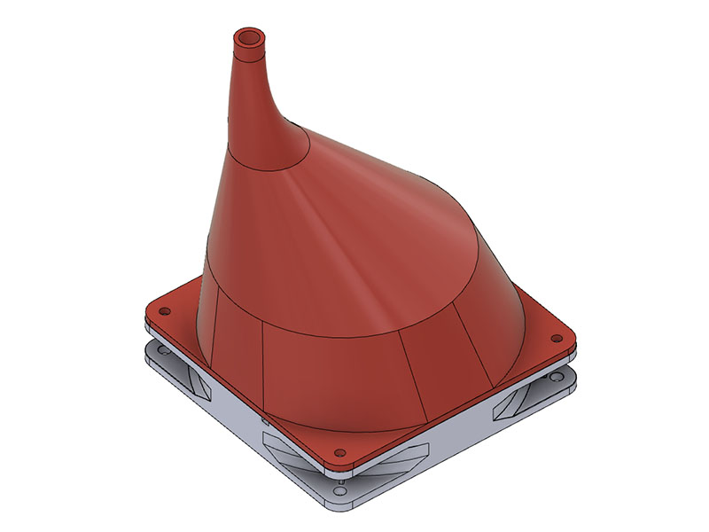
Certainly would have a lot air flow. There will be a lot of pressure in the funnel. So it won’t be very efficient, but I don’t think that will be a problem.
Another guy in the forum here and I are using airbrush hoses. I’m not quite sure what the thread size is, but maybe something that would fit those. Not necessarily threaded, but sized so that the hose end could be screwed on. Thats just my $.02. I could do some testing on my end once you have a model finished if you want.
After some quick searching, it looks like 1/4" or 1/8" BSP threads. The hose I have has 1/4" on one end and 1/8" on the other.
I could put some relief valve M5 threaded holes in it just in case it is too much air & plug as needed. I will test it with a make shift tinfoil funnel on it before printing the 5+ hour print. A little off topic, but I am still dialing in my Zyltech Gear 3d printer. I am not used to a bowden extruder & will probably switch a direct drive on it at some point.
There will be almost no airflow out of that funnel.
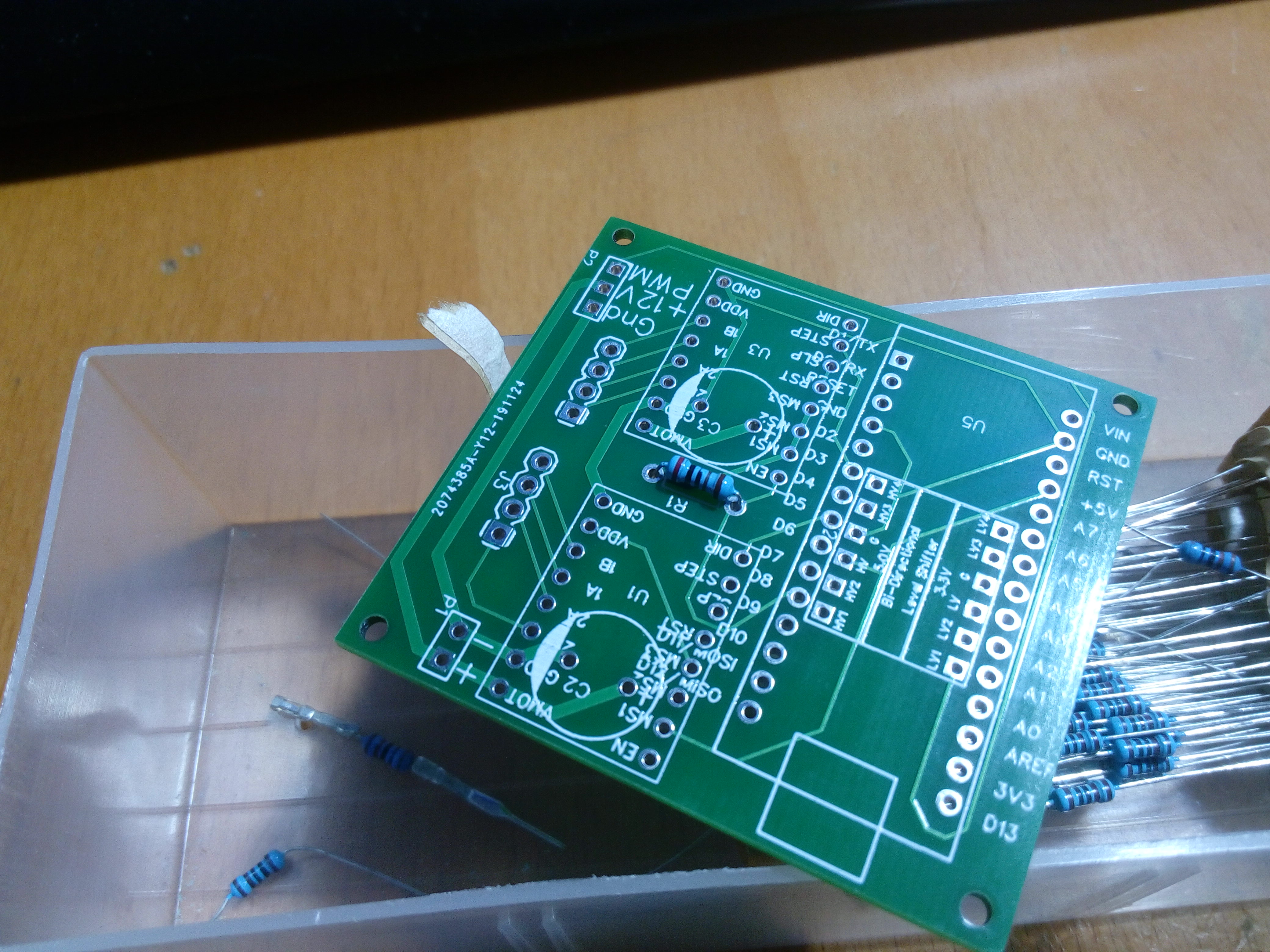
I am back to same problem with this board as previous board. I ran one burn test yesterday that was about 25 minutes & went well. Turned the machine off & unplugged it for a few hours & came back later to run another test and now this board has same problem as I was experiencing with other board & only thing I did was unplug it & plug it back in. I did not notice any static electricity in my shed. I have been connecting it to a windows laptop, so maybe I will try using the pi connected to it to with the v1pi & see if that buys me anything. I do have a couple of arduino unos with cnc shields I could test it with next if that doesn’t work. I also have a skr 1.3 board with a blown mosfet on the hotend which would not be needed for a laser, although that board would run Marlin & might have other problems I have not noticed as I think static did get that board.
I might go ahead an order one of those oscilliscopes next week to test these boards. Of course it will probably be March before getting it.
Got image rastering working.

4 Likes
Here are some photos of some work I did today
Line art[Lake Tahoe Topo Map]

And
Raster Image

8 Likes
After reading Static charge (?) causes spontaneous restart of my RAMBo - LowRider CNC / Troubleshooting - V1 Engineering Forum, I am wondering if I should add a ground wire to my controller board. I am using a brick 12v P/S that only has 2 wires to the wall plug. Didn’t seem like I had a static problem though & if I used a battery P/S when using this portable there is no ground connection. Any thoughts on this?
Looks like my Oscilloscope I ordered on 12/13 will be here today. China has gotten a lot better with their shipping times. Think they came into a different port this time. Anything going thru the New England states around NY seems to be extremely delayed. 6 parts I ordered in September went beyond their 90 day guaranteed delivery date. Guess those parts will eventually get here, but went ahead & ordered the parts I need from Amazon to populate the boards Mike designed. I am also going to swap the P/S I was using on that laser engraver & will use the P/S I had on my MPCNC from several years back. That should take that variable out of the equation & seems like that is a good suspect.
I got some part from China off the slow boat (for my outdoor lights project) and a sweatshirt mailed usps from Pennsylvania about the same time is still MIA.
I ordered some computer parts on eBay last month. They shipped from New Hampshire on Dec 17th with a estimated arrival date of the 22nd and they arrived in a sorting station in Florida on the 27th. I’m thinking maybe sometime this spring they’ll arrive in Oregon, unless they go overseas from Florida…
3 Likes
Since I know absolutely nothing about oscilloscopes, I did a search on youtube for some tutorials & found a few that reference what looks like the scope I got. I found this one in particular to have a lot of detail. KYE Tech “DSO Shell” Oscilloscope: A Detailed Video “User Manual” - YouTube
2 Likes
Good find Dave, I learnt some new things about these scopes…
Glad I could help. I am finally starting to wire up the board you designed. What gauge wire are you using for the 12v connection? I was wondering whether to solder 2 wires directly to it or add a 2 pin header for it. Looking back in my thread, it appears this should only draw .2amps at the most.
Would this wire be sufficient for the Power supply. I got a confirmation that it measures 21 gauge. http://www.zyltech.com/new-zyltech-1m-40-pin-male-female/ This way I could solder a 2 pin male header & use the female connection on the board & male connection on the P/S.
I’m not sure of the gauge I used but it was the thickest I could squeeze into a dupont connector and it was most probably under rated for the task  If the stepper drivers were tuned for maximum torque from the motors then you might expect 2 Amps per motor…but I think I used smaller stepper motors and didn’t bother tuning for maximum torque as it wasn’t going to be needed for this application… so I used figure of eight red/black ~24SWG…I THINK! So your 21 gauge will be a better choice.
You would probably need to drill a new hole if you wanted to fit a terminal block as the pitch is currently for a pin header @1.27mm
1 Like
Ok, thanks for the info. I have only measured 0.2amp max, so probably will not be over 0.5a. I will probably cut the 1 meter length wire down some as I does not need to be that long. Alternately, I a wire from an unused China hotend should be big enough for this connection. I tested that for fit yesterday. I got 67 solder joints done yesterday & should get the other 25 or so today. I am going to use a different P/S this time that worked on my MPCNC to take that variable out of the equation. I also noticed while soldering the resistors that the hole spacing could have been a little wider since I could not get my 2 resistors to lay flat. Had you noticed that?