12V or higher - I’m running 19V on mine because I had a convenient old laptop power supply. My version of the CNC shield supports up to 35V DC.
I am back to piddling with this laser engraver again as I got side tracked on other things for a while. After hooking up the custom board Mike designed, it does not seem to work. Probably a bad solder spot somewhere, but I didn’t see it. Anyway, since I have a spare Arduino Uno/CNC Shield 3 from Arduino UNO Compatible CNC kit + Shield + 4x A4988 Drivers - ZYLtech Engineering, LLC , thought I would play with that. I powered it ok to flash the grbl firmware & set the Vrefs on the DRV8825 & that part seems working ok. The DRV8825 were already set correctly, but wanted to make sure as I have run into an instance before where the VREFs on one board are not necessarily the same on another board.
My question is what is the standard way to hook up a laser to the UNO shield? I was going to run the +5V PWM off the “Z-” pin as @dkj4linux mentioned, but not sure where to connect the 12v lead. The only spot I know for sure that has 12v is the input voltage connection, but would prefer a pin connection somewhere. I saw in another thread where someone used the spindle on/off connection to control the laser, but did not see any wiring pictures. Does anyone know the best way to hook this up to this board?
The 12V presumably requires the whole current for the laser. So make sure that whatever you connect it to can handle that much current. I would probably connect it to input power, or to input power through a switch (so I could intentionally turn it off). Since it is 12V, you can probably find a neat automotive one that has a built in 12V LED and everything.
1 Like
You could pick up the +12V and Ground from the unused 4th stepper driver header pins, the upper right two pins. It goes through the fuse though so if it blows it isn’t big enough!
Any spindle on/off connection would have to be via a MosFET so not on a uno cncshield…a RAMPS perhaps, or via a separate mosfet driver driven from SpnEn pin, but you would still need to source a +12V supply.
With the Uno/CNC shield combo, the safest thing IMO is to directly tap/use the +12V input power to the shield, as Jeff has recommended. This insures a shared ground reference for the PWM signal and power passed to the laser module and a length of appropriately-sized wire is almost always a better choice than guessing/hoping the etched traces on a cheap board can support the laser module’s entire required current.
1 Like
Yes… but dupont connectors are rated at 2.5A, which means they are good for up to a 30
Watt laser  …yeh…you are probably right Dave…best double up the wires at the input connection screw terminal block.
Ok, I will look for a little 12v switch locally & see what I can find. We have quite a few auto parts stores in this small town, but maybe Walmart would be less expensive if they have one.
Actually, I might use Mike’s suggestion of using the 2 pins on the motor connection. I checked the voltage to make sure I had the correct pins to use. That is the kind of pins I had been using on the other boards so my wire harness is already made up. For someone else’s reference later, here is the pinout for the DRV8825 pins from Pololu - DRV8825 Stepper Motor Driver Carrier, High Current
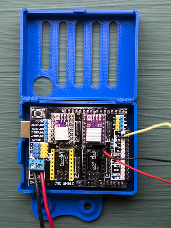
This is what I have for the laser wiring. Do I have the yellow wire on the correct pin? I have it on the Z- endstop, but not sure I have it on correct side as I can’t find a pinout layout for the UNO board showing which is actually D11 pin. I also made a hinged case for the UNO board.
2 Likes
That should be the correct pin - Z+ and Z- are the same from a signal point of view, and all the “black” pins along the edge are ground.
Ok, Thanks. I was wondering why I saw a couple of wiring diagrams where they used the Z+ connection.
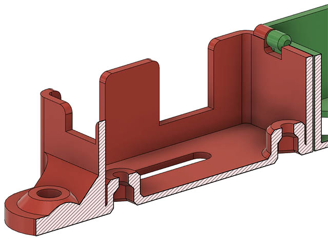
That is a nice case Dave, is it deep enough to clear the drivers heat sinks?.. could possibly fit a fan on the top too… got an stl to share?
It has about 3mm clear of the top of heat sinks. I will post the fusion 360 file on thingiverse when I get a chance, but here is the STL file. I also have one for several other boards, like the Pi, PI zero, your custom board and a SKR V1.4. I have most the dimensions as variables in fusion 360, but do have to spend a half hour or so when changing it for another board. I modified someone else’s original idea of this that had it for a pi zero I think. Uno_CNCV3_HingedBoardMount v3.zip (67.1 KB)
1 Like
I added this with the fusion 360 file for it to thingiverse. Also added the step & STL file for SKR V1.4 board. If I make other board cases, I will add them to this same spot. https://www.thingiverse.com/thing:4877889
1 Like
Separating the two halves of the stl was interesting! I assume you didn’t print yours in one piece. First one just off my printer - thanks.
I printed it as one print. There should be enough clearance to separate, at least mine did not have a problem. I can change that tolerance if it is too tight for you. Not sure off the top of my head what the clearance was, but probably .2mm
Cool!.. I wasn’t sure it that would work! It is possible to get the two pieces back together if you print them separated
That is good to know & glad it worked for you. How did the M3 nut traps work for you? I had 3 of the nut traps that worked & one was loose & had to put a small screwdriver in it to tighten it. I used .25mm clearance on those & probably should have used .2mm. I have a hinged case for your custom board also if you want it? I made 2 of those holes M2.5 & the other two, M2 & drilled out the board for the M2.5 where there was room to do so. I did that because I could not find M2 locknuts before, I have since found some on aliexpress.
I always struggle to get the supports out cleanly so always resort to using a soldering iron to heat the nuts up and push them in, any left over support material gets re-molded!
I’m ok for my board mounting, I printed something ages ago… but thanks anyway…
Argggg…M2… finding an allen key is a pain…
I avoid using supports unless absolutely necessary. I have the M3 Nut traps chamfered at top so no support is needed for them. I also add a short chamfer at the bottom in case it is a tight fit, I can get it started easier.
1 Like