If you want to duplicate what I did, here are the components I used…
the ball-valve…
hose and assorted fittings…
and the air pump…
– David
If you want to duplicate what I did, here are the components I used…
the ball-valve…
hose and assorted fittings…
and the air pump…
– David
I will take a look at those tomorrow. How quiet is that air pump? I got a little carried away today with drawing up a design. I took 2 designs on thingiverse & combined and modified them some. Here is what I have so far. The focusing ring works really well by itself. probably need to simplify it to more like your design.
I don’t find the air pump objectionable at all. It’s not silent but not loud either… not that I’d notice however – I’m also hard of hearing 
I always set the focus to about 55mm or so from the bottom of the lens assembly… and leave it there. Then I fit my nozzle (about 50mm long) to the lens assembly with the air inlet oriented where I want it… leaving focus about 5mm beyond the nozzle. I cut and use a 5mm step-gauge to then adjust the distance, nozzle to material, on my CO2 laser (no Z-axis)… or use Ryan’s focus script to fine tune using my diode laser’s fully-implemented Z-axis.
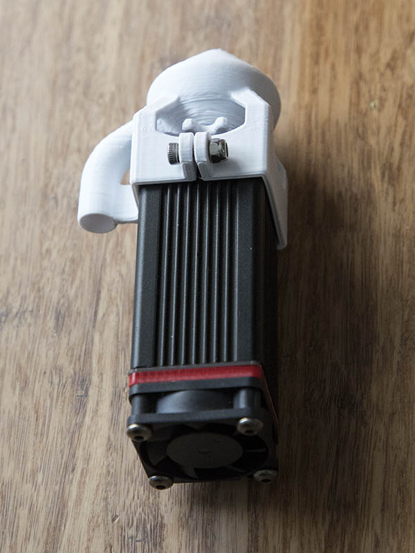
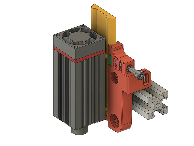
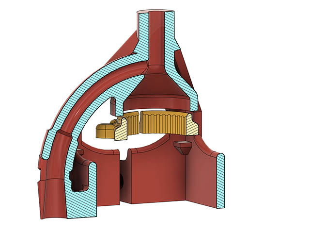
I opted to order the aquarium pump I linked in a previous message & have started working on a mount for it. Since I currently do not have a Z-axis (which I may make a manual one similar to my rolling plotter mount), think I worked out a way to use a modified version of this wheel adjuster with the air assist. Laser focus adjustment wheel by Pawpawpaw85 - Thingiverse . I redrew this in fusion 360 so I could modify it. I mostly just shortened the outside diameter to fit within my air assist mount. I left 22mm wide openings to get my finger in between to adjust. I have to print this air assist with supports, but only in the center. I have 2 screw mounts on the laser but also added a bracket squeeze mount in front as I am not sure the 2 screws are enough to support it. I looked at putting a flat brim at bottom of nozzle & printing from that end, but then I have the overhangs of the rectangle collar which do not have enough room to really taper up because of the screw mounts on the laser. Here is what it currently looks like.
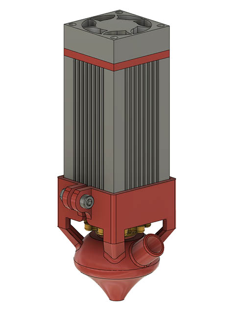
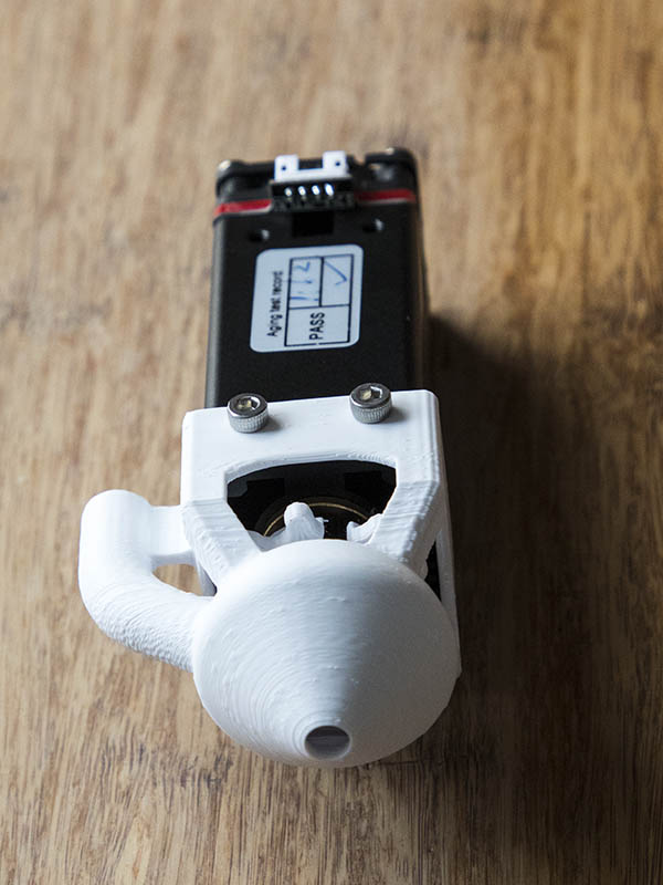
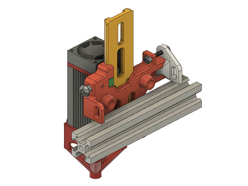
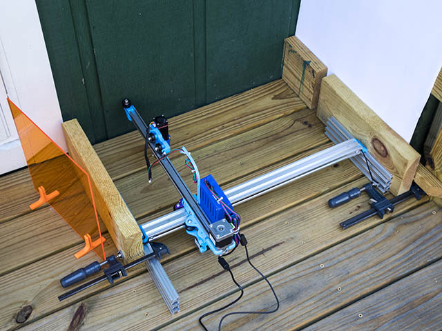
I adjusted the design a little. I noticed there was less than 45 degree angle on part of the nozzle on 1st print & made the air input angle up to the top of square adapter so only part that needs supports is in the middle. I have plenty of room to get my finger in to adjust the focus and should easily mount to laser on the machine without taking anything off. Pump should come in today. Here is what it looks like attached to my spare laser.
Some of the air assist nozzles I’ve seen designed for 3D printing actually close over the end of the cone with a very thin layer so that the laser punches through on the first use, keeping the aperture as small as possible. This ensures positive pressure inside the cone, preventing smoke from eddying up against the lens.
Does enough air get through that tiny hole to clean the burn? Seems like that would be a pretty high pressure of air coming through that might cause other problems.
I’m only reporting what I’ve seen in other designs similar to what was posted above. I guess it would depend on the laser’s focal length and the volume of air you were pumping. These seem to me to have to do 2 things at once:
One design I saw had 2 conic sections, one that pointed down close to the workpiece in order to focus the main blown volume for “air assist” and a shorter, blunter cone protecting the lens that got a smaller amount of air from an internal baffle.
Currently my laser engraver is sitting under about 1/4" of dust as it’s been a while since I’ve used it. My personal DIY’d solution was a .035’ welding tip screwed into aquarium tubing and heat-shrunk to a piece of 12 gauge copper wire which was in turn attached to one of the existing laseer head screws. This let me “aim” at the focal dot for air assist, but didn’t provide any lens protection.
Thanks for the clarification and the idea. Now that I have dry fitted this hose with the pump, I can see the volume of air will not be very much. Think I will redesign this nozzle some to make it thinner & maybe a smaller opening in the bottom. Putting this on my laser engraver, I also noticed I need the mounting holes & collar on opposite side so the hose is on the supported side.
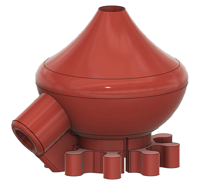
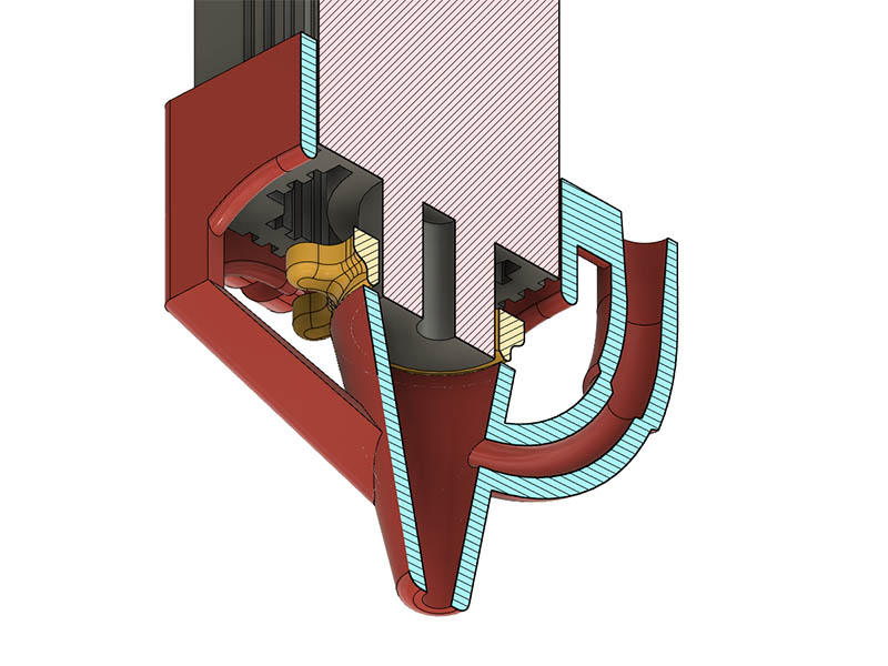
This morning I realized a bowden tube might work for this air tube & was happy to see it fit tightly inside the aquarium pump tube. The volume of air coming out of it felt stronger. I changed the design to accommodate it & made the nozzle smaller. The volume of the inside of the nozzle went from 10.52cm3 to mere 2.12cm3. I plan to put a slit in the 1st part of tube connection to wire tie it tight on there. It is currently a 3mm opening at bottom of nozzle and input. I might test printing a smaller hole to see if I can go much smaller than that.
For a quick test, slap a piece of tape over the end and let the laser make the opening.
I might try that tomorrow. I has some little orange dots stickons that might be good, but will try painters tape if I can’t find them. First test fit today looks like I do not have the bracket quite square and laser is missing 3mm opening partially. I changed it to 4mm & added some bumps on corners to make sure it square when tightening bracket. I was right about those 2 screws mounting it to laser not being enough to keep it square. I also shortened the end of it by 5mm as it was hitting a 2x4 I had under it.
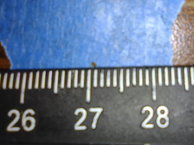
Here is closeup of the shot thru the tape. Looks like the laser might be a little out of focus, but is about 5mm higher that surface I focused on.
Think I have printed my final version of this air assist bracket. On the latest version I added corner stops for the laser to make sure it was squared up & changed the bottom opening from 3mm to 4mm diameter.
I have been looking for a way to do a manual Z-axis for a while & think I came up something light weight modifying this design on thingiverse: Ortur Master II Air Assist with Z axis level by ChatToBrian - Thingiverse
I recreated the design in fusion 360 just the way he had it except for the air-assist portion, then incorporated into the carriage design I have. I shrunk the width of his dovetail as much as I could, but still had to widen my wheel spacing by 2mm to miss the dovetail cut. I added 5.5mm high spacers to the laser hole locations to give clearance for the wire connection. I still cut a 2mm groove in the mount for good measure. I was using 3 wheels before, but had to switch to 4 wheels. I have a M4x30mm screw for the setscrew with M4 nuts. Here is what the design currently looks like.
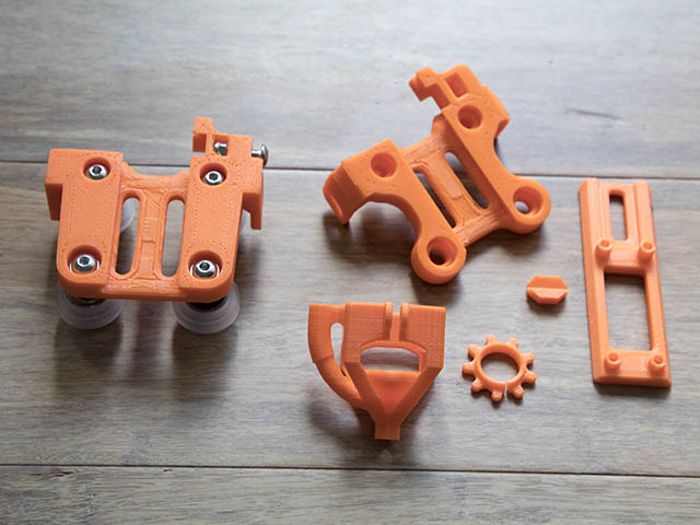
I adjusted the design a little more to cut out some more plastic & use M5x20 screw with locknut instead of the M4 screw & 2 nuts. I also changed the original small press fit pusher block to have no overhangs on the carriage mating portion. I cut out 18% volume from the design & it came out 12% lighter. I test fit it yesterday & seems good. I think this will be a nice light weight manual Z-axis solution for this cantilever. The laser mounting holes are 2mm shorter at the bottom than the top since the air assist mount is 2mm thick and mounts at bottom. Here is a photo showing assembly of 1st design & all the unassembled parts of new design along with air assist bracket. I am going to make another slider 25mm longer as I only have 12mm height to adjust lower if I set laser at current height of other carriage.
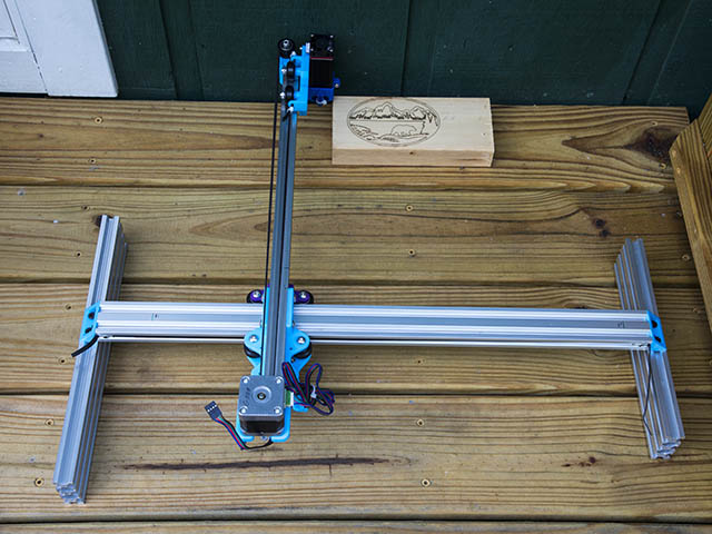
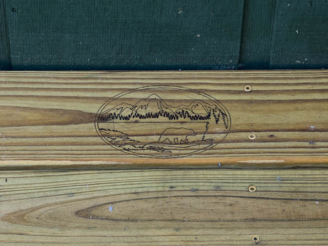
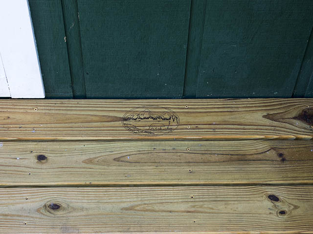
I plan to burn this little graphic on the inside board of the inside deck board I redid last summer & will not change the carriage to the new design until after I finish that since I have 2" longer reach with other design which gets me about 1" from end of cantilever. I have to wait for a dry day to do it.
I uploaded this design to thingiverse along with the fusion 360 files. Laser Manual Z-Axis Air Asist and Focus Wheel by GeoDave - Thingiverse
I finally did the engraving on a deck board. One thing I forgot after changing controllers was to set $32=1. I went back over it a 2nd time after changing this so the pen up burn moves would not be as noticeable from a distance as you can see from last photo. Anyone have suggestions for taking out those lines? I was thinking of trying steel wool or a really fine grit sandpaper. Over time they will probably be less noticeable. I was going to video it with my older DSLR, but it stopped after only a couple of seconds. I think the bright light made it auto shutoff. I thought it might do something to my camera which is why I used my older camera. I clamped the side 2060 extrusions to 2x6’s so it would anchor it & that worked well.
That’s pretty neat. I wonder what I should laser around my house? Does it etch concrete? 
I didn’t think about trying concrete, mostly because I didn’t think it would work. I do have some concrete that is not so clean. I bet it would burn thru the grime.
I have not really had a belt tensioning for this design other than just pulling the motor tight, so thought I would add one to the carriage. Shouldn’t be much more weight. This gives me 10mm of tensioning using a M3x20mm screw with locknut. I used a similar method on my folgertech Delta printer awhile back & borrowed some of the design from that. I am only doing it one side since the M5 Z adjustment is on the other side. I also increased the distance by .5mm between top wheel holes & bottom eccentric holes as the eccentrics were all the way out with no adjustment. The distance before was what openbuilds used (39.7mm using 2020 V-Slot) & works well with aluminum cut carriage but apparently need a little more for plastic.