Current limit Stepper drivers drv8825

Hello, i’m not sure for the adjustment of the stepper.
It’s difficult because my english is not really good and it is difficult for me to understand the video here https://www.v1engineering.com/assembly/ramps-wiring/

I need to adjust the current VREF of the driver.

The motor : NEMA 17, specs : 2,8V and 1,7 Amp

Is this formule is good ? VREF = 1,7/2 = 0,65 ?

And for the X and Y, we have two motors in parallel, so we need a Vref of 0,65 x 2 = 1,7 ? But we can’t have a vref up to 1,1 with the steppers.

Thanks you for the help !

V x A = W
2.8*1.7 = 4.76W
4.76w/12V~.4A so we set that in volts.

and 2 steppers get .8, but that is max you can always run them a bit less.

Cool, thanks for your help Vicious !

I was about to ask a similar question, but I bought the kit.

The kit has these motors in them, right? http://www.automationtechnologiesinc.com/products-page/3d-printer/nema17-stepper-motor-kl17h247-150-4a-for-3d-printer

Those are 4.2V and 1.5A, so using your equations above, I would get:

4.2x1.5=6.3W
6.3W/12V=0.525A

So for X, Y, it should be set to 1.05V, and for Z, 0.525V

I understand the power equations, but then why do you take the input current, in Amps, and use that for the reference voltage?

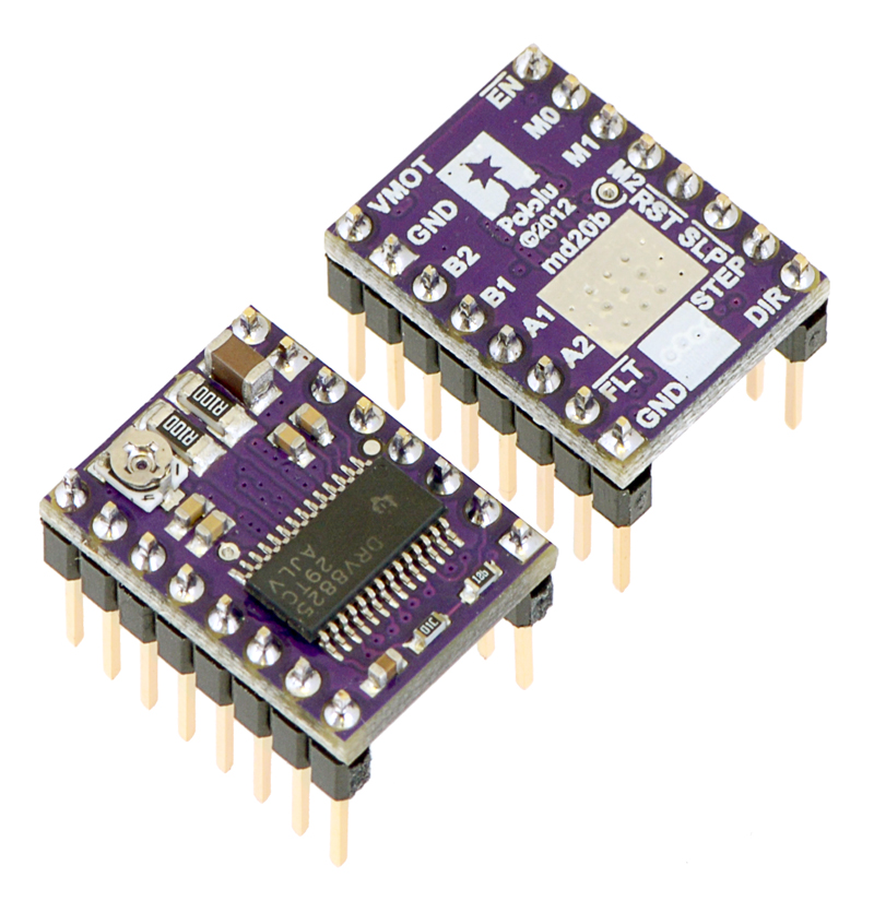
From the data sheet (https://www.pololu.com/file/download/drv8825.pdf?file_id=0J590 pg 12) it shows:
Ichop = Vref / (5*Rsense)

Pololu uses a 0.100ohm Rsense, so I see where they got their equation.

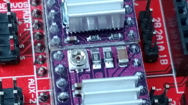
But, I went ahead and tested it. I put the Y driver in 1 Step mode, and connected an ammeter in series with one of the coils, powered it up, used the LCD to command some Y motion, and then stop. I got 0.65A, which, because it’s in single step mode, and there’s some loss is probably closer to a limit of 1A, and the Vref was set to 0.7V. Is it possible the drivers in the kit have a 0.140 Ohm, or similar Rsense?

I don’t know if you tune the drivers before you ship, but it looks like you did, because I had X, Y: 0.7V and Z: 0.49V.

It’s too early for this kind of thing. I can’t pretend to be super knowledgeable about this. The equation I always put up is the quick and dirty to explain more about working from watts than the Amps in the stepper datatsheets. Once a week I get asked how to hook up more drivers because theses can’t handle the steppes people want to buy, we both know this isn’t true. We can pretty easily run 4 of our large 17’s.

There is another equation further down the data sheet more for micro stepping I believe.

I do set the drivers before I ship the boards and I do intentionally set them low. at .7v they are fine by themselves above that and you start needing active cooling so you don’t get thermal shutdown. With the drivers and steppers I am currently shipping (and active cooling) you can set the pot to about 1.1V before you start getting the steppers to warm for PLA mounts. I also noticed you don’t get a very noticeable power difference above .7v. I tend to not run things at there max, for longevity.

Haha, sorry. Maybe I shouldn’t have jumped onto this thread to ask. You’re also at the bottom of a tunnel of thoughts that has built up since right about when the website went down. And then there’s the additional pain of you having to deal with that yesterday, sorry.

I’ve never used steppers or drivers at all, except the ones in my wanhao i3, which required zero knowledge from me. So I’m also trying to understand it myself. I’m a software engineer, but I also have a degree in electrical, so I’m trying to get my head around it (you’re not responsible for my education though, so if I’m bothering you, I won’t be offended if you tell me).

When I did my testing, with no microstepping (trying to just follow that video you linked to), I did try to move the potentiometer to 1.065V (which is 1.5Vx0.71 for single step) and I measured the Vref, and it was about 1V-1.1V (I didn’t write it down, sorry). That seems to correlate with your rule of thumb. It also had a very slight hum to it right when I got to 1V. The only thing is that I was only running one motor, and I think you should be able to double that to hit the theoretical max, since X, and Y have two motors.

I’m fine with leaving them where they were shipped. At least until I start making a mess of chips.

Can you answer these two specific questions though?

  1. Is the drv8825 the same as the pololu one? Does it have the same Rsense as those chips? I’m either not understanding something, or this has a different Rsense.
  2. When you were talking about your 0.7V and 1.1V above, you were talking about driving two of your stock motors, or just one?
Haha, sorry. Maybe I shouldn’t have jumped onto this thread to ask. You’re also at the bottom of a tunnel of thoughts that has built up since right about when the website went down. And then there’s the additional pain of you having to deal with that yesterday, sorry.

Its all good, I just needed to finish my coffee. I really do want to know the correct way to tell people but these steppers have tons of conflicting data bout them, Don’t even get into microstepping and torque. Real companies with real data, completely opposite each other.

I’ve never used steppers or drivers at all, except the ones in my wanhao i3, which required zero knowledge from me. So I’m also trying to understand it myself. I’m a software engineer, but I also have a degree in electrical, so I’m trying to get my head around it (you’re not responsible for my education though, so if I’m bothering you, I won’t be offended if you tell me).

You just became our resident expert! You now have some homework…Kidding… I think you’ll see it is always a ballpark. You can greatly under and overdrive steppers, because they step.

When I did my testing, with no microstepping (trying to just follow that video you linked to), I did try to move the potentiometer to 1.065V (which is 1.5Vx0.71 for single step) and I measured the Vref, and it was about 1V-1.1V (I didn’t write it down, sorry). That seems to correlate with your rule of thumb. It also had a very slight hum to it right when I got to 1V. The only thing is that I was only running one motor, and I think you should be able to double that to hit the theoretical max, since X, and Y have two motors.

I’m fine with leaving them where they were shipped. At least until I start making a mess of chips.

Always my suggestion. Try it stock only fix what needs fixing…like the stupid z nut lock, next on my list.

Can you answer these two specific questions though?
  1. Is the drv8825 the same as the pololu one? Does it have the same Rsense as those chips? I’m either not understanding something, or this has a different Rsense.

They are supposed to, but might be different. I have a few dead ones I can try and get the little guy off and test it, if it isn’t marked.

2) When you were talking about your 0.7V and 1.1V above, you were talking about driving two of your stock motors, or just one?

Yup

Oh yeah, markings.

The kit drivers:

Compared to the pick at pololu:

The R100 are the 0.1Ohm. So that’s the same on both. The rest of the board isn’t laid out quite the same, but the pololu one has a “01C”(10kOhm) and a “12B”(1.3kOhm). The kit ones have a “152”(1.5kOhm) and a “103”(10kOhm), but in the opposite locations. I think these are the same, with just a different layout. So I’m not sure why I’m measuring a different ratio of Vref to Ichop. I’m half tempted to buy one from Pololu, and see if theirs does what it says. BTW, this site is cool: http://www.hobby-hour.com/electronics/smdcalc.php

So it’s still a mystery, and I’ll leave it at 0.7V until I see a problem.

I do get 2 different styles in. The pot is opposite on them, when I get a batch of the other ones I will have a look to see if the layout is different. I tested a batch this morning and didn’t get any of the other ones but when I do 'll take a picture.

Your formula in your initial post is correct, albeit with a small error in maths :wink: . The formula for calculating the current limit on a Pololu DRV8825 driver is “Current limit= VRef x 2”.
For the 1.7A stepper that is 0.85V for Vref.
If you connect 2 motors in parallel then each will only receive half of the current, so at that 0.85V you’re only going to get 1.7A/2=0.85A per phase at each motor.
To double the current you would then need to increase the VRef but you won’t be able to output 3.4A anyway as the maximum spec output current for the DRV8825 is 2.5A and in reality the Pololu will only give 2.2A due to the 0.1 ohm current sense resistors.

Bear in mind that if you do decide to use the full 2.2A with the 2 steppers in parallel (that’s 1.1A to each motor), then you will most definitely need a heatsink and active cooling for the IC.

Most people seem to automatically go for parallel when connecting 2 stepper motors to one driver but in this situation I’d be more inclined to wire them in series.
This will allow you run them at their rated current if you wish as both motors will receive the full current of the driver instead of the reduced amount in parallel.
At 0.85V VRef, both motors will receive 1.7A per phase if you wire them in series.

There are pros and cons to wiring stepper motors in series vs parallel. In series there is slightly less torque at high speeds but in this situation you wouldn’t have been running them at full current in parallel anyway so it should be win-win. Also if you’re using the machine for milling/cutting then torque at high speed isn’t what you’re looking for anyway as the feed rates tend to be relatively slow.

I don’t think that’s right, with it set like that your would be able to fry an egg on your steppers. Setting it to .8v on the dual axis and the steppers are warm. You turn it up to 1V and they are pretty hot. At least last time I checked. I spent a full month at the beginning trying to squeeze all the power out of the 42oz/in steppers we had then. Pretty sure the resistor comes into play in that formula somewhere.

The 1.7 amps you are using is also for a lower voltage, That is why I always show the wattage conversion. The steppers I sell are 1.5A at 4.2v, much lower amperage at 12V, .525A that seems pretty solid because I have never turned vref past 1.1v.

I’ll try turning it up to 1v again and see if these are the steppers that get hot. Pretty sure they are. I had them on overdrive for the 4 head printer. I’m all for real world testing, you guys figure out the numbers I’ll try not to burn down the house.

The thing is though that the steppers won’t be getting a constant 12v(or whatever your input voltage is). You’re not meant to do the ohms law calculations in this situation, that’s the stepper driver’s job. You set the current that you want it to aim for and it will chop the voltage at high speed to try and maintain that current.

For example take your motor with a coil current spec of 1.5A at 4.2V. That means your motor’s coil resistance is 2.8 ohms. Also assuming a Pololu DRV8825 with .1ohm sense resistors.
If you set up VRef to 0.75V then you’ll get 1.5A max. At the time that 1.5A is flowing, 4.2V will be applied across the motors coil (V=IxR) (4.2=1.5x2.8)
If you set VRef to .5V then you’ll get 1A max. When the 1A is flowing, 2.8V will be applied across the coil. (2.8=1x2.8).

The motor won’t actually get fed the full input voltage constantly (12V in this case) as that would damage it. (I=V/R) (4.29=12/2.8)
That would end up with over 4 amps flowing and that motor would be toast pretty quick.

You’re right about the motor being hot with the VRef turned up. At it’s rated current a stepper motor can be quite hot. I guess in this situation it’s all about finding the balance.

All that said, that’s just the theory on how to properly adjust the current limit. We don’t necessarily need the motors running at their full current/torque either. We just need enough torque to mill at the feed rates we want without skipping steps or having issues.

Well that makes a ton of sense. Much more clear now.
I know most of the common NEMA 17’s at full specs are 100C, way to hot to be useful for us. So we are using them at about half full power just because of the heat issue…I think.

So .7 to 1 is our useful range, unless you use the aluminum mounts (good heatsinks and won’t warp). Then max out the drivers with good active cooling!?

So…the next question. How much extra power is really at the top end of that torque curve? If it takes an extra 50C of heat to get 5% more power, not worth the hassle.

Thank you for clarifying that.

Any suggestions for telling people how to adjust their drivers? I get the question pretty often. I would love to put stuff like this in a FAQ’s page.

The aluminium mounts should be a good heatsink for sure. Plus it’s a good job for the machine to do and will look great after.
The torque should be fairly proportional to the current but the heat dissipated will be proportional to power (and to the square of the current (P = Isq x R)). So by dropping the current back until the steppers are cool enough we’ll only lose a little bit of torque but we’ll get rid of a lot of heat.

BTW I’m part way through my build (still waiting on some parts), and that middle section… wow. The more I put together, the more I see how much time and effort you’ve put into this awesome design.

As for the best way to adjust the steppers, the best way to go about it is to use the “Max Current = Vref x 2” but that won’t help with how hot the steppers get.
For the people that buy kits from you, find the best balance on VRef for torque vs temp without active cooling and give them that. If the customer wants to add active cooling and bump up the current later then they can.
For anyone buying their own steppers there’s not much you can do except tell them to use the VRef x 2 formula with their own motor current and advise them not to run the motors hotter than the glass point of the PLA (around 60 deg C).

That does all make sense C, thanks. Any idea why what I was measuring was lower than that? Is there something I’m doing wrong when measuring the current?

I think you need to tell people that the max current is set by Vrefx2, and that the drivers for X, Y are powering two motors, so the current to each motor is halved. Then you also need to tell them some rule of thumb, like setting the value to 50% of the max, and not more than 1V.

Setting the Vref to 0.75V for X, Y and the stock parts is 1.5A for two motors, or 50% of the max. Setting it to 0.5V for the Z motor is setting it to 2/3 of the max. So I think you’ve got a ballpark number. Free advice always comes with a YMMV, and I think that’s as close as you can get.

I just re-read your post there. So you were in full step mode with a VRef of 0.7v and you measured 0.65A input to the motor coil?
That’s off by a bit alright. In full-step mode you should be getting 70% of the current limit. That’d be (0.7v x 2)x0.7=0.98A
Now saying that, nothing about this process is stable so the current and voltage will be changing all the time. I’m not sure how that would affect the reading you’re getting. Did you measure the current while the motor was moving or while it was holding position?

I can’t test my own to verify for you yet because I’m still waiting on my DRV8825’s to arrive. I’m just using some A4988’s that I had lying around to test my setup until they get here.
Once they show up though I’ll gladly test it to see if I’m finding similar readings.

I was using the arduino mega with RAMPS board to do it. They are disabled by default, so I went into the menu, told them to move (prepare -> move axis -> move 1mm -> Move Y) and then I let it just sit there at that position. This was with only one motor, but I don’t think it should matter.

Ya the number of motors shouldn’t make a difference. The current would be impossible to measure accurately with an ordinary ammeter while the stepper is moving anyway as it would be constantly changing.
As for measuring when the motor is holding, I’m not sure exactly what the driver will be doing at that point but I’m guessing it’s still pulsing the coil at high frequency so that could be throwing off the readings that you’re getting.
What are you using to measure the current? A multimeter in series with one of the coils?

That’s exactly what I’m using.