I’m working on permanently adding a Raspberry Pi 3B+ to my 3D printer LAACK enclosure setup, and I’d like to add a “shut down/boot up” button as spelled out in this article. I’ve got a couple of these LED lighted pushbutton switches leftover from building my MPCNC control box, so I’d love to integrate the indicator light from this article. The good news is I’ve wired it up and put all the code in place and the button works, and so does the light. The bad new is that the button is rated for 24V, so the 3.3V from the Pi GPIO is just barely visible.
I’m running this all off of a 12V power supply, so I’ve got access to plenty of juice, and 12V is plenty to light the button up, but I’m not enough of a circuit designer to have confidence in building my own solution from scratch. Is it as simple as adding a PNP transistor with base to the PI, collector to the 12V supply, and emitter to the light connection on the switch?
MOSFETs get driven my voltage. Regular transistors need to be driven by current. The tricks for all that is just picking the right one.
There are also good driver circuits for less if you have more than one channel. I can’t remember the name of them now. 2808? 2008? That’s gonna bug me.
Keep in mind that your button is meant to be driven off of pure 24V. So they probably have a good resistor in there already. That means that 1) any diagrams that add a resistor in series with the led don’t need it. And 2) If you were daring, you could try to replace the resistor with a smaller one, which would make it pass more current (be brighter) at lower voltages.
Be careful driving too much off of those pi pins though. They can only push 20mA or so. The failure mode is damage.
These are great for a few RGB LEDs because they have 7 channels. IIRC, the 2003 version sits on the negative lead of your load and the 2803 sits on the 12/24V side. I see a long lead time on the 2003 version, but some other variants, like 2002 are in stock. I would have to read more, but I think the difference is a little more or less output current.
This will only ever drive the single LED embedded in the button. I’ve pulled the button apart as far as I can without permanent damage and can’t see a way to get to any resistor that might be in there. That’s why I was thinking a transistor might get this (very limited) job done.
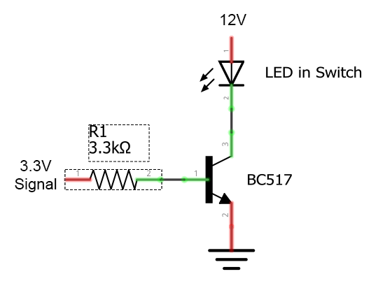
I dabble with electronics with no training…just what I pickup on the internet. I asked myself what I would do in your situation with the parts I have on hand. So I’ll toss a circuit out, and the more trained/experienced people on the forum can correct me if I’ve blundered.
The BC517 is common, cheap, and incredibly forgiving given its high current gain. I could probably use any resistor between 330 ohms and 1M ohms on the base, and the circuit should still work.
Ordinarily this circuit would blow up the LED with too much current, but as Jeffe pointed out, the unit is intended for 24V so it will already have an internal current limit (resistor). So this should work just fine. Just about any NPN (not PNP) should work I would think. I would think 2N2222 would be okay too, if that’s what you have on hand.
I played around with several transistors from an Amazon assortment I picked up a while back, but didn’t get results that knocked my socks off. For now I’m settling for driving the switch’s led with the 5 v available on the first couple of GPIO pins on that row. They’re not software switchable like in the article I posted but they make the button bright enough to tell when the power is on.