One other thing I am still trying to figure out in my head is able management for the 2 Y end stops. Its a long table so that cable would be so long. I’m thinking to bring both of them to the midpoint of the Y axis travel and then attach them there, then just leave a smaller length of cable that would allow the router to reach each extent of the Y axis. Does that make sense?
Mount each of the two switches to their respective y-plates.
Cabling for one side is short (assuming your board is also mounted to that same y-plate). The opposite end (far side), just run the end stop cable through an x-axis tube or in the aluminum angle plate. Take the same path of the far side motors.
If that doesn’t make sense let me know and I can share photos. My X and Y are swapped so I’m running in “portrait mode” but the same wiring principles apply.
No that makes perfect sense. How do you have the switches attached to the Y plate so that they make contact? I’m not sure how they would bump into something on my table
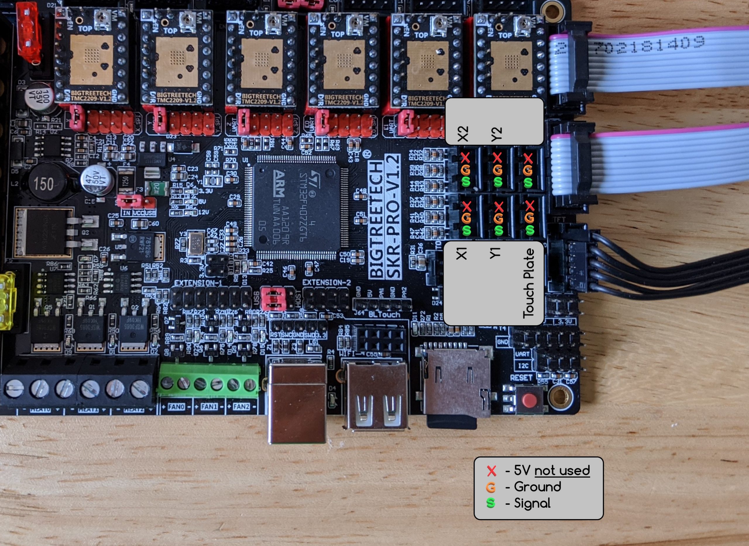
So just to be clear on this setup:
X1 is for well, X motor
Y1 and Y2 are for both Y motor (so along the table)
X2 is for Z2 Max
The one without a label is Z1 Max
And touch plate, as the name implies, is actually Zmin
Did I get this right ?
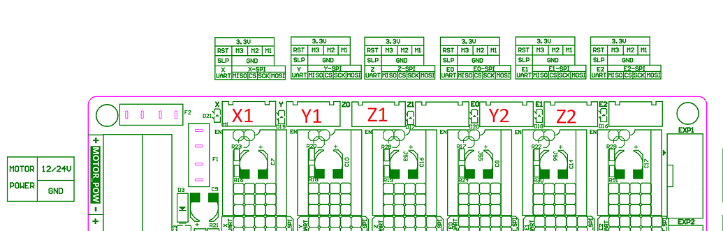
But if so, that’s not coherent with the wiring diagram here:
The endstops are a little weird, but try the documented way first. There are some goofy remaps because of the Z homing up.
When the machine is running, you can verify each endstop with M119 (it responds with the endstop states). If you find an error in the docs, let us know or make an edit and get credit as a doc contributor. But I think they are correct, there was a close inspection a while ago and we haven’t heard complaints since.
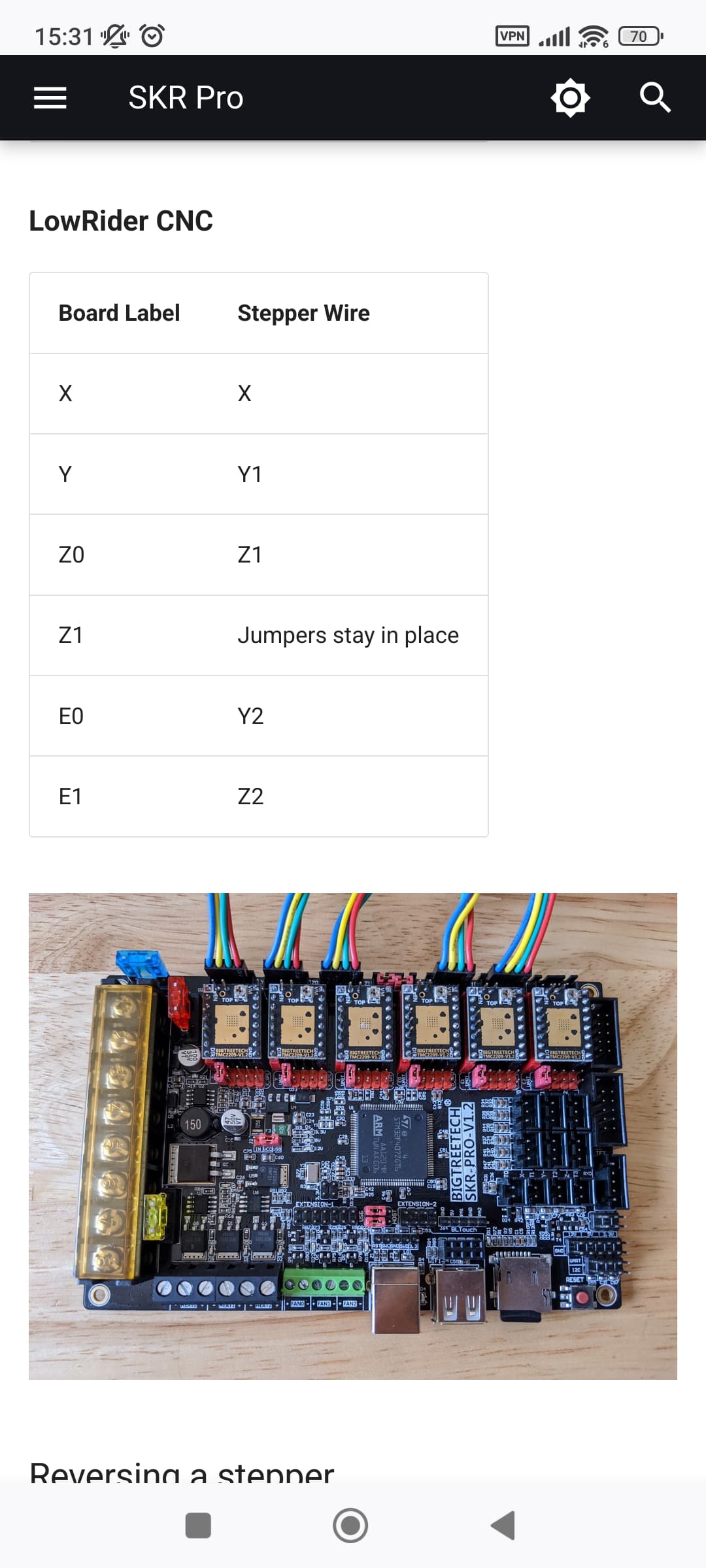
Slow progress, work and family is getting in the way
Dual end stop are setup for Y, single endstop for X
As for Z, I had overlooked that it was homing up (which in retrospect makes sense), but that means the current physical setup I have is not appropriate.
Would anyone have any recommendation on how to mechanically mount the switches for Z homing ? Our X axis is not quite // to the table, so if we use Zup homing, we need to find a way that the switches will trigger so that each Z motor is exactly at the same distance from the table
Also, I would welcome a link on the complete workflow, including touchplate.
I’m assuming, everytime I switch the tool:
Homing across all axis
Move to Zmin with the tool setup and a touchplate probe, define zero
For a LowRider 3, I would see no reason to mount them in a way that is different from what was designed.
For a LowRider 2, I used a switch mount on the bottom of the YZ plate and a “paddle” on the Z tube to trigger it. I’d do the paddle a bit differently if I were to do it again, but the idea worked. I had more trouble with the Y stops than the Z ones, all told.