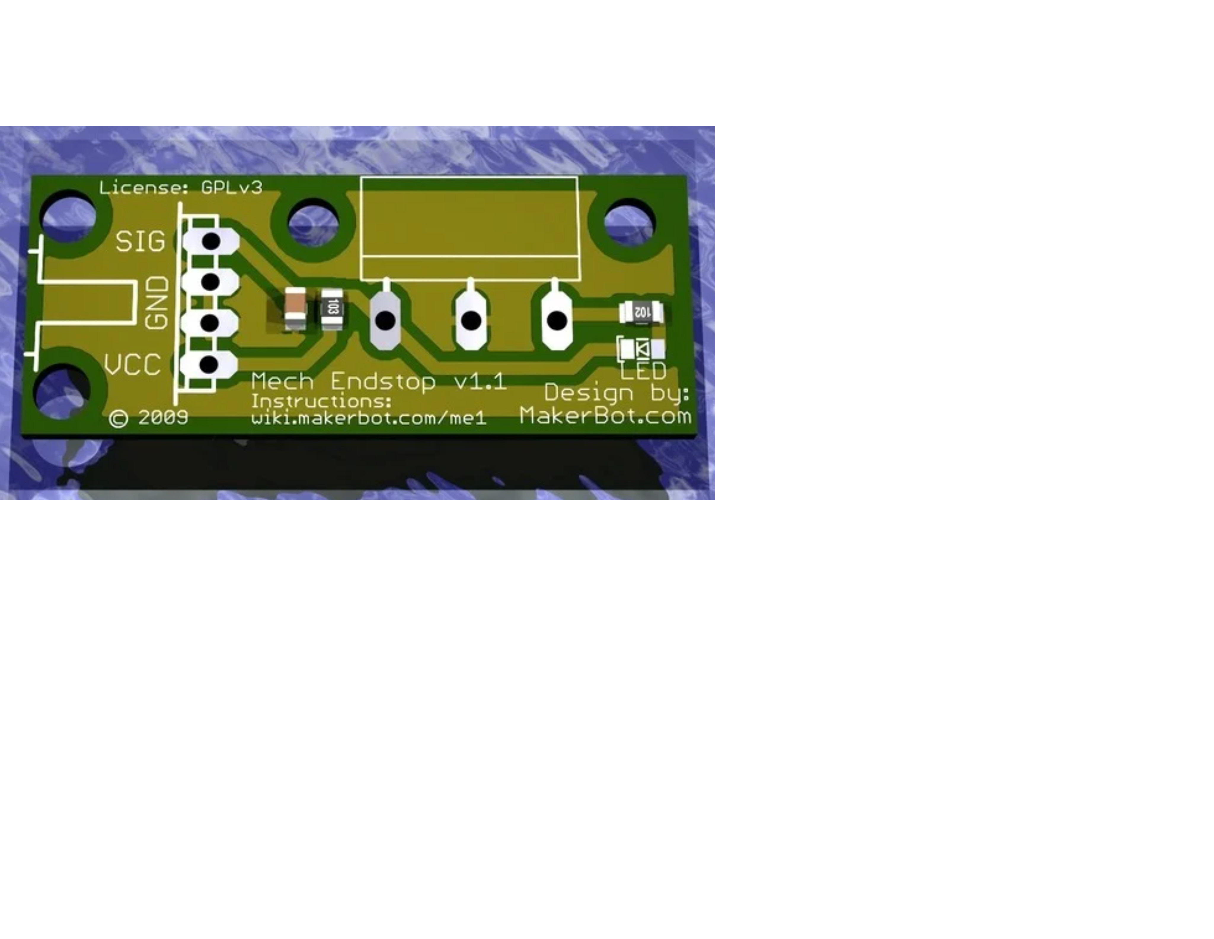
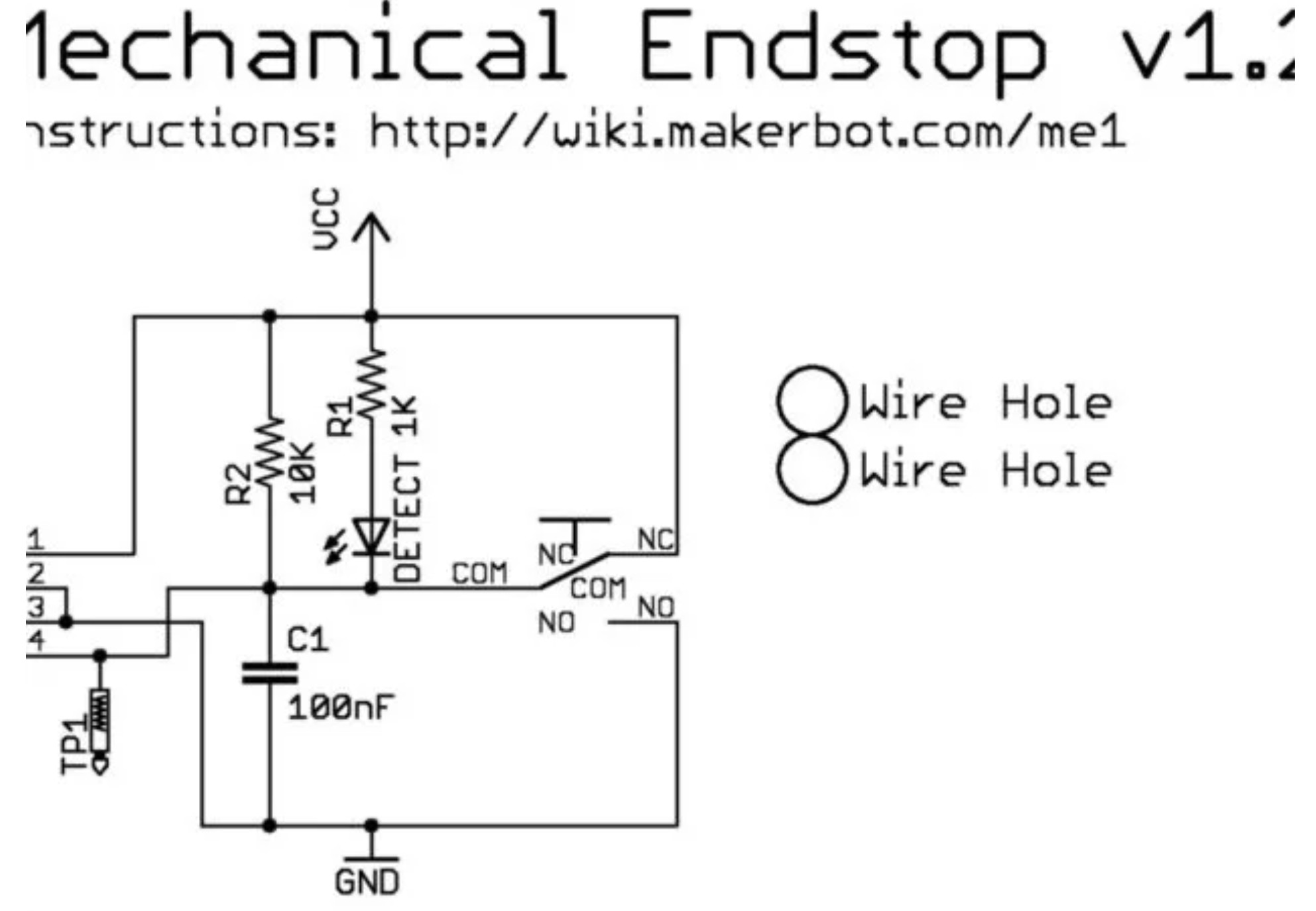
I have these endstops I ordered and my rumba32 on the switch input, has signal, ground and vcc. should I just rewire the switch to work from no between ground and signal. Or just plug this in. don’t want to burn it. here is the schematic of the little switch board. I 'll probably not the resister off and wire straight to the switch.
Occasionally questions about switches like these come across the forum. Usually the best course of actions is to either not use them and buy just the switch, or to de-solder the switch from the board. Note that if you are building a Primo, I don’t believe the standard mounting holes in the trucks will work with the circuit board attached. You will have to rig some other way to attach the endstops.
I’m just a hobbyist when it comes to electronics, but it looks to me that all you are getting from this circuit is an LED and a bit of smoothing/debouncing from C1. If you are building a primo and want to use this board, I suggest not rewiring the board but instead changing the firmware to expect NO switches. They should work fine as long as you are careful with respect to ±s on the control board where these plug in.
It is this section of configuration.h that controls whether endstops are expected to be NC or NO:
// Mechanical endstop with COM to ground and NC to Signal uses "false" here (most common setup).
#define X_MIN_ENDSTOP_INVERTING true // set to true to invert the logic of the endstop.
#define Y_MIN_ENDSTOP_INVERTING true // set to true to invert the logic of the endstop.
#define Z_MIN_ENDSTOP_INVERTING true  // set to true to invert the logic of the endstop.
#define X_MAX_ENDSTOP_INVERTING true // set to true to invert the logic of the endstop.
#define Y_MAX_ENDSTOP_INVERTING true // set to true to invert the logic of the endstop.
#define Z_MAX_ENDSTOP_INVERTING true // set to true to invert the logic of the endstop.
#define Z_MIN_PROBE_ENDSTOP_INVERTING true // Set to true to invert the logic of the probe.
Note that the NC configuration is considered a bit better since if a connection to the endstop is broken, homing just fails rather than keeps on running.
The biggest problem is that the switch mounting holes n the MPCNC (Or MP3DP) will not accommodate these PCBs so mounting is enough trouble that I did not use them (Even though I have loads of spares) for my V1 machines.
what I thought, I just knock off the resister and the diode and build a mount to be safe. running that vcc voltage on the circuit makes me nervous. thanks guys.