what do they mean on my board it has stop x-, stop x+, stop y_ and so on are these separate switch what’s the - and the + here is the board.
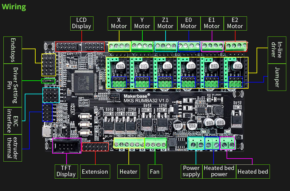
Each endstop has a ground, 5V, and signal. Be careful not to use the 5V pins on endstop switches. Those are for powered devices, like an inductive probe.
The X+ is what you would use if you were homing to the positive end of the axis. X- is for xmin. Same with the other axis.
1 Like
so this is what I use on the lowrider right. I am wondering about the endstops. this is 3.3 volts by default. how do you wire the switch up, using 3 points shown on the board there? so i would just use signal and ground for my connection to the sw
Yep, signal and ground. Polarity does not matter. Stay away from the endstops with the leds, just use a simple switches like this or this. Note Jeff’s statement about not using the 5V pin is because if you do, a closed switch shorts power to ground and often burns the pin out.
1 Like
Your board has the signals marked at the end of the endstop block. V for voltage, G for ground and S for sense. The passive endstops we all (almost) use connect between G and S, leaving the V disconnected.
1 Like