I’m trying to place 2.5D cuts in sheet acrylic. Used TinkerCAD to create designs and exported to STL. It also offers export to SVG but that only exports cuts on the bottom layer, and my grooves and engravings are on the top layer. So STL it is.
IIRC it does automatically switch to 3D mode when you load an .stl. But I have to confess the difference between 2.5D and 3D seems to be one of those concepts I think I get, I think I get, I think I get, uh…maybe not.
2D is through completely. 2.5D is something like a pocket, dado, rabbet that doesn’t go all the way through, or carving. 3D is tool movement in all three directions at once, like cutting the inside of a bowl.
If you have 2.5D part, and estlcam is treating it as 3D, then it will not try to understand the geometry the right way and it will just “approximate” the shape with left-right and up-down cuts. Kiri moto does a little better and will follow edges with a finishing pass.
But doesn’t 2.5D also allow you to do something like a ramp. It’s only 2axes moving but I was under the impression changing the XY plane in motion was what elevated it from 2D to 2.5D?
i.e. The start and end points have X,Y coordinates but one(not both) can be changed while Z changes so all 3 axes are involved, just not at the same time, thus 2.5D, at least that’s the way I understand it.
I may not have it right. I’ve been wrong about it before. In my mind, if you start with a 2D drawing, it can’t be 3D milling. But there is definitely a difference between just milling all the way through vs. doing some depth limiting. I put everything that starts with a 2D drawing, but isn’t through cuts into the 2.5D bucket. Carving has moves in all three directions, but it is not what I would call 3D.
I’ve been wrong many times but to me, true 3D carving allows motion along all 3 axes simultaneously while 2.5D allows motion on all 3 but only 2 at any given time. IOW, a straight ramp with constant Y but varying Z along the X axis would be 2.5D while a spiral ramp descending in Z around a circle would be true 3D.
For some reason I never really thought of it this way, now that I do it kinda makes sense. I believe at least in the past, there were some healthy price differences in some CAD programs between 2.5D and 3D.
Estlcam can do waterline for 3D STL, but this is not going to work as well as splitting the design into one or more 2D patterns as SVG or DXF.
If there is really no way to extract 2D artwork from the top, your local OpenSCAD evangelist would point out that you could use it to load an STL, cut with a plane near the upper surface and export a DXF.
SVG export is on the origin plane. To get the top, either rotate your object 180 degrees, or drop it to a negative height. For something like Ryan’s LCD holder, you can drop it part way and get the interior features that don’t come to the top. (Though the SD card slot is an exception. You would need to put in a block where that is in order to get the lines.)
I like TinkerCAD for being quick and intuitive. I’ve made designs using it that are way beyond what it’s really good for, but it really is limited, and not the best for designing for the CNC router.
This is a brilliant solution for my problem, and is probably all I need. Don’t need a fancy solution today, I just need to get my product done and can revisit doing it right later. It should work fine, because the parts are all flat acrylic sheet with both full cuts all the way through (currently being exported) and partial cuts for slots (not being exported). By moving to a negative height I can have it get both.
Thanks, will give it a shot then will try to remember to come back and report if I need something else.
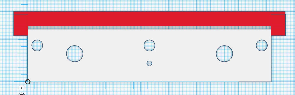
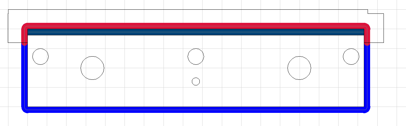
Since I have grooves that touch edges of the acrylic sheet, the export treats those as if they are the actual edge. To solve, I placed cubes and blocks (in red below) along the real edge in Tinker. In Estl, I chose my 1/8" bit and am cutting along the inside edge of those blocks using the engrave tool, manual left side. Select all the important points then hit Enter. The edge of this engraving touches the groove. The groove itself is pocketed to its appropriate depth using the engraving tool, same procedure. Select the points of the groove then hit Enter. I chose manual paths and left side so it cuts to the correct side of the line.
An important step is the red blocks are moved 0.01mm away from the left and right edges of the white rectangle. You can perhaps see it on the top screenshot. This is important because if they perfectly abut, the TinkerCAD export treats red and white as all one unit, so there are no lines in EstlCAM to draw a shape around.
It’s a hack, but it works.
TinkerCAD looks like this. Between the red and white areas there is a grey shaded area which is a half depth groove.