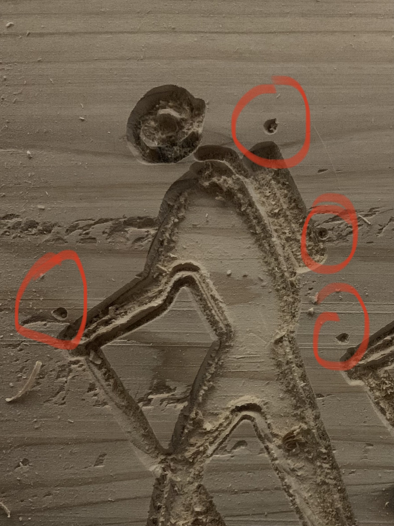
Hi. So I’m testing a 50mmx50mm print using estlcam, and when it’s finished, I see a couple of spots where the z axis unnecessarily carved small holes. In estlcam, everything was contained within the figure.
I have checked the x and y axis belts and they are right. Also, I’ve checked the z axis grub screws and they are on there tightly.
Any advice on how to fix this would be appreciated
It looks to me like you ran the sme code more than once, the area to the right looks like the hand and walking stick, and the one divot there looks like the same positioning as the one leftmost.
It does also look like the machine is having trouble actually carving the art. The lines look crooked and inconsistent.
If you could zip the Estlcam project file and the artwork that you’re using, that might help, maybe the gcode.
For starters though, it looks like something isn’t rigid enough for that speed and depth of cut. Try reducing the depth per pass or the bit travel speed until you at least get lines that look correct.
What bit are you using? This looks like it might be something like a 20° V carve bit
Thanks for the reply. I think you were right and I probably ran the code twice. Now it makes sense why it asked for a tool change halfways between the job.
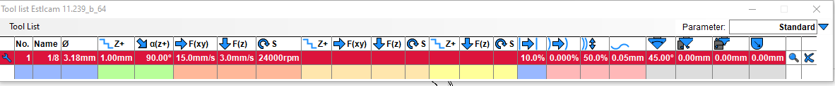
I was using a 45° V carve bit for that carve.
I plan on trying again in the morning using the attached as you requested. Also, I will be trying the 1/8 single flute from this site.
The tool settings I used are the ones from this picture
Hiker2.zip (423.6 KB)
For one, setting the maximum carve width as something less than the maximum dimensions of the drawing, and then allowing the depth to remain automatic is going to do some weird things, particularly if you’re using different widths everywhere.
I would suggest that you set a maximum carve depth as something reasonable for your tooling. 1 or 2mm given that you have the tool defined as 1mm/pass will give much more reasonable carve times. You can then set a reasonable line width to either give a carve of the complete figure, which would be to set the maximum width as something that will allow the entirely of the piece to be carved.
As is, it looks like Estlcam is getting confused generating the gcode. If I enlarge the .dxf, I get some gaps and oddities in the drawing, so I’m guessing that some of the problems are related to that. The shapes aren’t properly closed, and that will definitely result in some weirdness. I’d say that it looks like you generated the .dxf file from the .jpg file. Perhaps something didn’t translate quite right. I tried some bitmap tracing in Inkscape, and got some varying results, with some wobbly lines sometimes. Jpeg is a compressed format, so it does sometimes have some weirdness in it that doesn’t really show up to the eye.
If I were looking to do this as an inlay, for example, I would probably choose a large value for maximum carve width and a small value for maximum carve depth. I’d probably also import the .dxf into a CAD program and resolve it to a fully closed and constrained sketch.
1 Like
I will give that a shot. Thanks so much for the advice. I’m totally new to all of this and it’s been fun trying to figure it out. This community is great!