Hello! I have just started experiment with my newly-built MPCNC and I’ve had sucesss cutting out flat and 2.5d parts. Now I’m experimenting with carving, and using ESTLcam’s 3D free machining function.
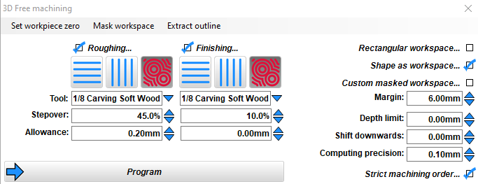
I designed a simple square cup with a rounded-out center. I’ve made several, and while my 3D model is precisely 50.8mm on each side, the carved cup is 49.5mm. I adjusted every parameter: allowance, stepover, margin, computing precision, and every time the size difference is the same: always 49.5mm instead of 58.8mm. I’m carving with a 3.18 ball nose endmill.
The inner dimention of the carving is precisely what it should be, so the entire model isn’t getting shrunk. The outer edges are just being carved in a bit too much.
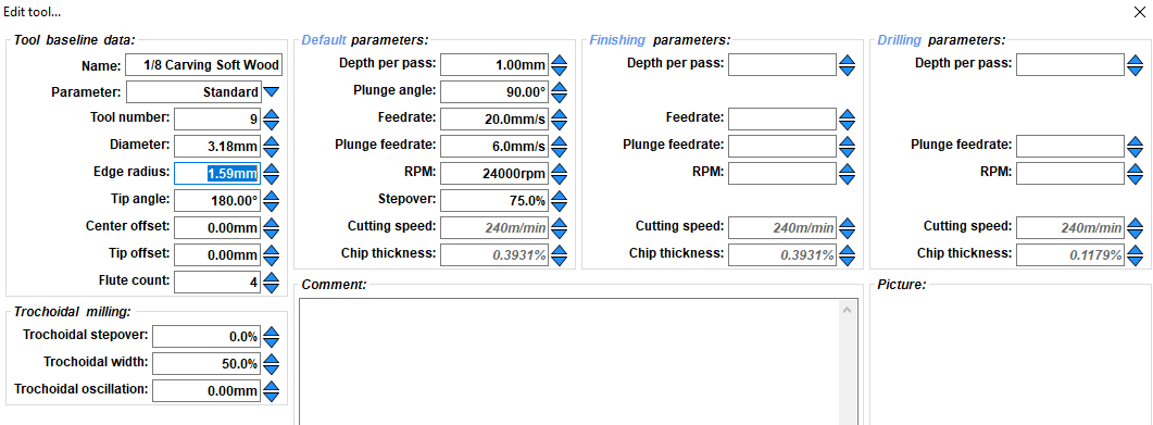
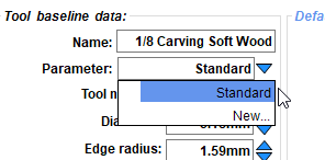
I haven’t tried 3D carving yet. What is that parameter you have selected in the second photo? If the CAM thinks the bit is smaller than it is, it would move closer, and remove too much.
I don’t actually know what Parameter means. The “Standard” is just what came with ESTLcam when I installed it, and I don’t know where to edit the features of “Standard”.
I’ve double-checked my Diameter and Edge Radius settings, and I feel like they are correct.
The few times I have had a similar issue (with Fusion, not ESTLCam) it was exactly what @jeffeb3 said. I had the diameter of my bit wrong and it would think its cutting 3mm when my bit was only ~2.6mm. Double check your bit sizes. Not what might be advertised as the size (this not not always accurate), but what calipers actually measure.
I have checked my bit with calipers and it’s 3.16mm (versus the assumed 3.18). I did a test cut with adjusted measurements and it doesn’t seem to make a difference.
As I mentioned before, the inner dimensions are carved perfectly. So something is going wrong only with the outer shape.
That’s why I was curious about the “Edge Radius” parameter. Maybe it is meant to be diameter instead? It would have to be a setting that only applied to the outside of the object.
I have changed the Edge Radius to match the diameter of the endmill, and nothing changes.
I took a measurement of the piece before it went into the finishing stage, and it measured at just a tiny bit over the correct size. After finishing, it was once again too small. So I suspect somewhere, too much is being removed during finishing. Or maybe too much is being removed both during roughing and finishing?
I personally use Fusion 360 for my MPCNC; though in this topic I am only suggesting it as a way to eliminate the software as an issue, not to try and convert you to use it over Estlcam.
Alright, I was able to successfully mill the exact same model using Fusion 360 to generate the gcode, and the model turned out perfectly - exactly the dimensions it is supposed to be.
So I think this verifies its an Estlcam issue. I could go forward and just use Fusion 360 but I would like to figure out what I am doing wrong with Estlcam.
Thats good that it works in Fusion 360, it means that its not likely a hardware issue and you just have to nail down the configuration to get Estlcam working. I am not experienced with Estlcam, so I can’t help you with any specifics.
If it were Fusion 360, I would say either the bit is misconfigured, or the tool path is set to cut on the wrong side of the line (or directly on the line). My advice would be to check similar Estlcam settings.