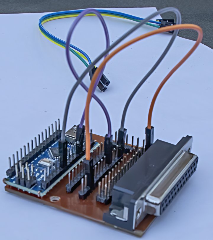
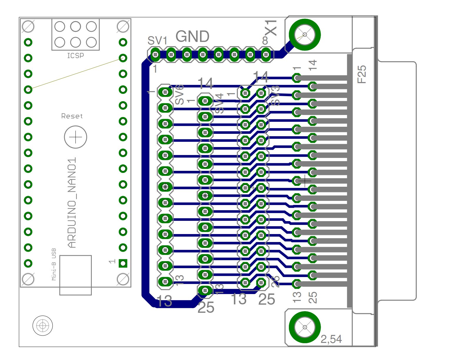
I was using MACH3 to a PC printer port but that computer died and I’ve had to settle on a solution using a USB connection. EstlCAM seems to translate my Gcodes to accurate cutting (GRBL might have done as well) but I’ve settled on ESTLCAM for now. The problem was adapting the USB signals to my breakout board which expects to plug into a PC printer port. There are many designs of breakout board available at very low prices which also expect a PC printer input and they all seem to use different pin sets for their signals. I have designed and built a small Circuit board which, using Prototype connector leads (available on Aliexpress, 40 or more for $3 or less) connects an Arduino UNO to a 25-pin D-connector in an entirely configurable way. A 26-pin header connection for a ribbon cable is also provided for signals which the breakout board does not handle. I’ve attached a .ZIP file here which contains Eagle design files, GCode milling files and photos to aid in reproducing the board.
startGet to trust level 1 by…
Entering at least 5 topics
Reading at least 30 posts
Spend a total of 10 minutes reading posts
Users at trust level 1 can…
Use all core Discourse functions; all new user restrictions are removed
Send PMs
Upload images and attachments if enabled
Edit wiki posts
Flag posts
Mute other users
I am interested in this also you are using estlcam as the sender and gcode generator firmware correct?
I am using EstlCAM solely to interpret GCode files and control my CNC routing table. I am generating the Gcode files using a User Level Program (ULP) from an Eagle CAD PCB design.
I have also used LineGrinder to convert a Gerber file to Gcode but that was a while ago and I used Mach3 to control the mill in that instance.
I wanted to make a PCB mill but I had no room in my workshop so I got rid of my workbench and made a 1200mm x 2400mm routing table which is now my workbench as well - and a PCB mill capable of milling 0.1mm gaps in traces.
I have been awarded a trust level sufficient to now upload the .ZIP file containing all the my data to create this adapter and have uploaded the .ZIP to my earlier post.
Here is a view of the single-sided PC board.
If anyone needs gerber files, I will generate those and upload another .ZIP containing them.
Just an update. For those needing a more permanent solution (as do I). Instead of using the prototyping leads to make connections I finished up wire-wrapping the connections (a connection technique from the paleolithic of the computer age - look it up on Wiki) and then soldering the connections after testing.
Wire-wrapping wire and tool are still widely available.