I plan on building the entire assembly, including every bearing, nut, and bolt in CAD before I build it for real. Wondering if anyone has put together a file that could get me a head start on it. Even if it was exported as one big STL file. A Solidworks assembly file would be a dream, I’m sure that’s a long shot, but why not throw it out there… 
Thanks,
Ben
Understandably, vicious has not released any of the actual cad files besides a dxf of the motor mounts and maybe a beta part here or there.
However, you have some options to use the stl files on thingiverse. Autodesk offers the full Inventor Professional to students. You could download it and do the assembly and then be done with it (or activate if you are a student). Inventor Pro 2017 actually handles stl files really well in assemblies. It can even give you an axis through a hole to constrain to. If you get an older version you can use the Autodesk Mesh Enabler, an add in for inventor, to convert the stls to a base feature. But the assembly will be sloppy at best.
Have you tried just converting the files in solidworks? I think he uses solidworks to create them. I had great success converting some step files at work in solidworks to sldprt files and using feature recognition. It even managed to give me the sketches, holes, and tap sizes.
Edit: had no luck easily converting to a sldprt in solidworks 2015. But at least you get what the mesh enabler can get in inventor. A ton of triangular surfaces. You CAN mate to them, but I wouldn’t rely on any exact measurements from an assembly assembled that way.
Hi Nerdy,
I also understand the reasoning behind not releasing native files, being familiar with dealing with support emails myself. I guess He's looking for even a little more control over the many variables that can occur during setup. As far as Solidworks goes, I think that for the feature recognition to work, the files would need to be STEP or IGES. If they were STEP or IGES I wouldn't even need to recognize features, since I really just want to build the assembly in CAD, not necessarily edit anything. Although it would be nice to be able to lay out different sizes of conduit to see what things would look like, even putting models of parts I want to cut into the assembly to see if things are fitting and such. Also would be really nice to be able to visualize and design any new accessories right within context of the assembly. Also design my table and see how it will look sitting under the specific configuration I choose to build.
Once again, I completely understand, however I feel it does put a bit of a damper on things, and if I want to do this right, I’m either going to have to settle for a half baked Solidworks assembly made up of STL files that are probably not mated up correctly, or spend a lot of time modeling these parts, something we all have less and less of these days.
Still, so very appreciative of everything, and looking forward to finally being able to cut my own parts, plus everything else you can attach to this crazy machine.
Thanks again,
Ben
Update: Solidworks will try to recognize features in an imported STL file, but the result creates sketches that are made up of 100s of tiny lines rather than nice sketch geometry, resulting in a file that is no better than the STL for assembly purposes.
Also, I started trying to assemble the STL files into a Solidworks assembly, and it was actually going ok for the corner (although mating is very tedious), but then when I went to add the 3/4" 6-32 screws I realized that it would be incredibly time consuming to mate them all in place due to no circular hole to mate to. 
My favorite new feature in Inventor 2017. It finds holes and axis through stl files in assemblies.
That’s legit. Any chance it exports a STEP or IGES with a real hole after it finds it?
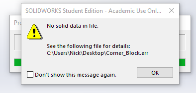
No luck getting a reliable STEP file out of it. Solidworks comes up with an error “No Solid Bodies Found” or something like that. IGES might be a different story, but it looks like my computer might be slowing Solidworks down when it tries to process the file. I can’t tell if anything is happening.
Solidworks says processing in the lower right, but it doesn’t seem to be doing anything. My CPU is at 10-20%.
I’m guessing that whatever Autodesk did to make Inventor good at using STL files is either screwing with the files or is some proprietary thing to give them an edge over Solidworks.
I feel your pain trying to make an assembly with only STL files. I did a few of them in Inventor before the update and the result is always sloppy if you cant get an axis or something good to mate to. Are you having issues with mating screws/bolts? McMaster Carr usually has pretty good solidworks files if you are willing to find the hardware and download each file individually. Sometimes you can mate to an axis, but usually you just have to do a concentric to the threads or another round part of the screw.
Cool, Thanks for giving it a shot. I’ve gone down the rabbit hole on this a bit over the past two days, and I think it may be a dead end. Looks like I’m either going to have to redraw all the parts, or take an insane amount of time mating up all the hardware into the holes manually. This is how far I got assembling the STL files when I realized the hardware mating issue.
No problem. It was something I was hoping to figure out too.
I’m not understanding the need to do a virtual assembly, you could have printed and assembled a real one by now? If it is just for looking at it, perfect hardware mates shouldn’t be an issue.
I can give an stl assembly but it is locked at that point nothing can be moved, I don’t understand the point. There are 2 or 3 full assemblies on thingiverse already and I think they are parametric as well.
Printing parts as we speak. I know it’s not necessary, I’m just a bit of a freak about having every nut and bolt of any DIY project I do all drawn out in Solidworks. See here, here, and here for examples.
It’s going to be weeks before I can finish printing parts because I can only do a few at a time. In the mean time I could be playing with the assembly in CAD, designing a table, thinking about next steps, accessories, laying out parts I want to cut in virtual space, seeing what different length formats look like. Etc.
I’ve been looking around thingiverse and found two assemblies, one seems to be the international version, I downloaded the other and tried to load it up in OpenSCAD, only some conduit and a few parts populated. I was thinking they were STL as well. Ill take another look.
I also thought it would be pretty cool to have it uploaded to Sketchfab so that people could spin the assembly around right from within a browser, or even on the front page of your site. Would really help them visualize. Might even end up with less support to do, because people could spin the assembly around and see how everything goes together. Could even have the sub assemblies shown. I’d be willing to create and upload all this, as well as keep it updated with any new components.
In my opinion, having the virtual assembly opens up so many more possibilities.
I totally agree about a virtual assembly being helpful. There were a few parts during the assembly where I was lost and just looked at other people’s build pictures to figure it out.
Hey Nerdy: Looks like inventor 2017 does let you reverse engineer STL files. Not sure it’s as easy as they make it look, but I’m guessing this method would output STEP files. I signed up with a student email, but the download is 11GB and my hard drive on my windows machine is full. Will see about clearing enough space this weekend.
I just played around with the fit mesh surface tool. Maybe i’m doing something wrong getting it set up for export, but this is what solidworks gives me when I try to open the step file I export from Inventor.
So it didn’t take long to do the fit mesh process? Are there any options for the type of STEP file to export, or any other export options you can mess with? Would another format like XT or IGES work? Sometimes parasolid files play nice. Solidworks also has options as you import a file if you choose STEP and then hit the options button. Is there a file size on the file you exported?
Good point with the file size. It is WAY too small (3.5kb). Something screwy is happening during the export. I have been selecting the STEP option in export, but it saves as a .stp. I manually added the e and it didn’t make a difference. So I switched to “Save As” instead of export and it comes up asking what I want to convert and has a variety of options. But the file size is still too small and solidworks gives the same error.
I really hate the stl file type. The only program that actually works good with it is TinkerCad, but you can’t do assemblies and stuff in it. Plus as someone that knows Solidworks, Inventor, AutoCAD, and Sketchup, I find Tinkercad incredibly frustrating to use.
Ugh, I thought we were getting somewhere. Might still give it a shot this weekend just for the heck of it.
I just found this. Not sure if it applies, but it appears to be a way of making a feature “more real” :
- Open the file.
- Right click on the feature and choose Copy Object
- In the COPY OBJECT dialog, choose “Create New”=Surface, and check on “Delete Original”
- Click OK–> here the composite will be copied as individual surfaces
- Delete the composite feature and save the IPT
- New an IPT file and do the derived feature operation
I am getting somewhere with this order of operations
Open STL file in Inventor (make sure Mesh Enabler is installed and set up as an add in)
Right click on mesh feature in the tree
Convert to base
Select base (not face) and click ok
Export file as STEP
Open STEP file in Solidworks
Run Feature Recognition, turning off features that the part doesnt have to speed it up.
Have a part going through feature recognition now. Hopefully it works or gets close enough to be good in an assembly.
!
Even STEP files would work for the assembly, feature recognition is just icing on the cake. How long would it take to fit the mesh on the more complex parts of the mpcnc assembly in inventor? Or are you saying it turns it in one operation?!
One simple operation to get the mesh done in inventor (any year).
https://apps.autodesk.com/INVNTOR/en/Detail/Index?id=6950391119076900441&appLang=en&os=Win32_64
Feature recognition may or may not work. It has been working on recognizing extrude features for a good half hour on the corner block lock. Much faster to just use the step file.

