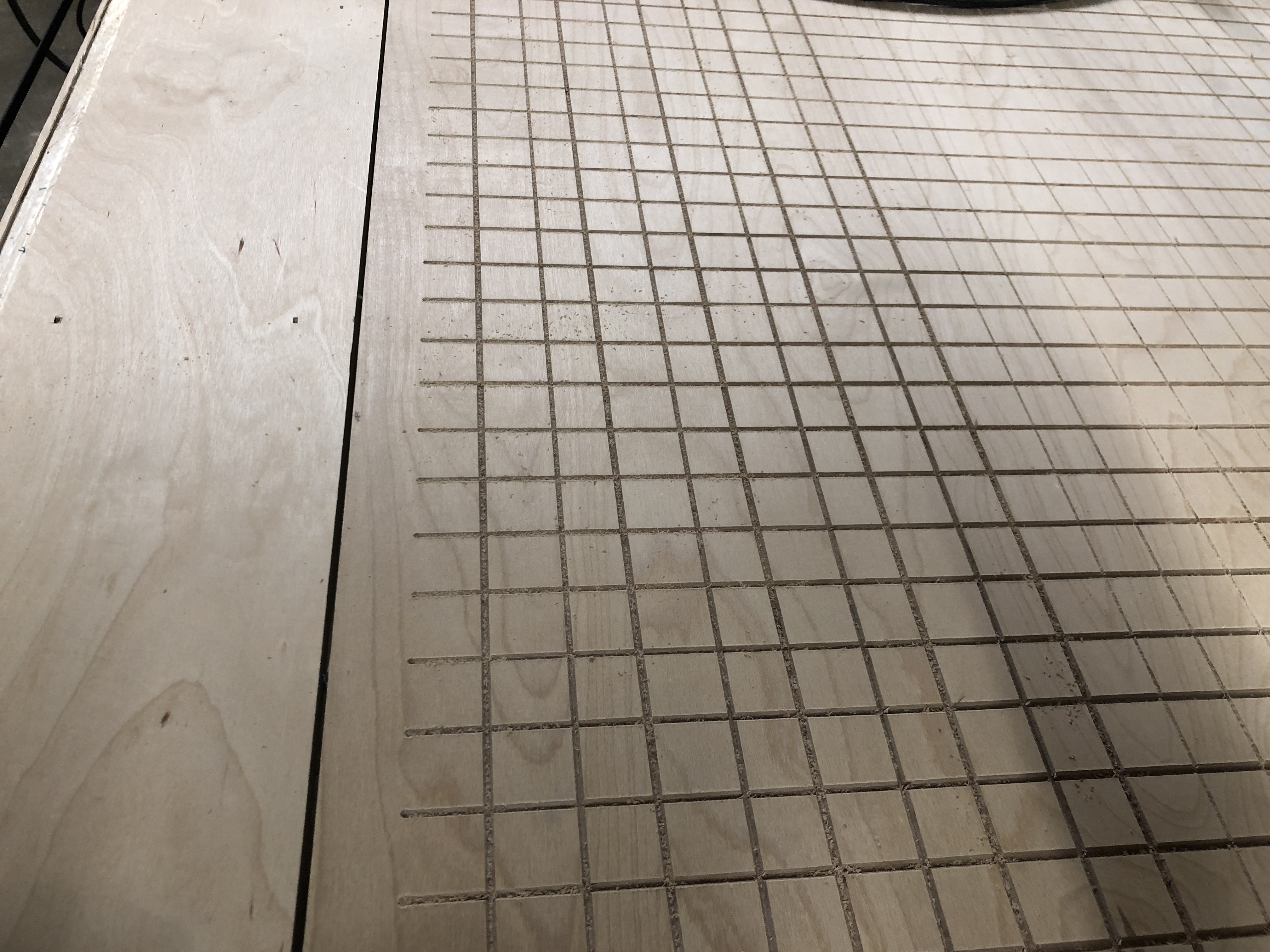
I thought I did enough testing to finally engrave this grid on my Lowrider table, but I was wrong. The grid is 1” squares and is basically the usable area of my gantry, about 34”x56”.
The gcode was done in Fusion and all the tests I’ve done have produced great cuts when working in a small area, about 8”x8”. I’ve even had the machine start cutting on one end, run the full length of the table and then return to complete the cut to test the accuracy.
My question is, what is the first thing you would check if your parallel lines were not coming out straight?
Slotting produces a sideways force relative to the direction of motion that (when cutting a straight line) can cause the tool path to start at the correct position and drift away to a consistent offset if the stiffness is not great.
But I’d say the size of the deflection is too large to be ordinary deflection. The LR2 should be much stiffer than that except in extreme conditions. Therefore I am thinking perhaps the grub screw on the X axis pulley might be loose, allowing it to slip a bit on the motor shaft. And also because loose pulleys are extremely common.
First thing for me would be check the fusion file, to make sure sure I din’t screwup.
second I would check the belt tension and the grab crew.
If everything check OK I will need a haircut… I would pull my hair out and make a song like this teacher… https://www.youtube.com/watch?v=1f7OwFqTnco&feature=emb_logo
The entire gantry may move side to side. Some LR2 builders who have encountered this have added tracks to guide the roller blade wheels to mitigate this effect.
Is the gantry square to the table? When I start my Lowrider, I apply light hand pressure to hold it tight against the Y belt mounts. I’ve shimmed one of these to get the machine square. My approach to adjusting this was to use the sharpest V-bit I had. I started up as noted above, then jogged to say X=1", Y=1" and jogged down the Z to just peck a tiny divot. I then jogged straight down the table to X=1", Y=55" and pecked another hole. repeat at X=33, Y=55, and X=33, Y=1. This should be a rectangle, and the diagonals should be equal length. If they are not, one of the belt mount can be shimmed to adjust the gantry for square. It is not necessary to “measure” the diagonals. I used a long strip of scrap wood, and put a small brad nail in one end, putting that in one of the tiny divots I just marked the opposite divot.
Alright. I have a lot of things to check for sure. I did put in tracks for the wheels and they have maintained the same Y axis after jogging back and forth a bunch. I’ll do some more testing and check the belt tension and pulleys.
Excellent! This wasn’t clear to me from the pictures.
Loose pulleys are the culprit in most of these cases. The pulley’s will work loose over time too, so it’s something to watch out for in the future as well. My Lowrider was cutting great for about 6 months, before I encountered an issue. Careful consideration of the nature of the error, and close inspection of the steppers while jogging the machine around made it clear I had a loose pulley…
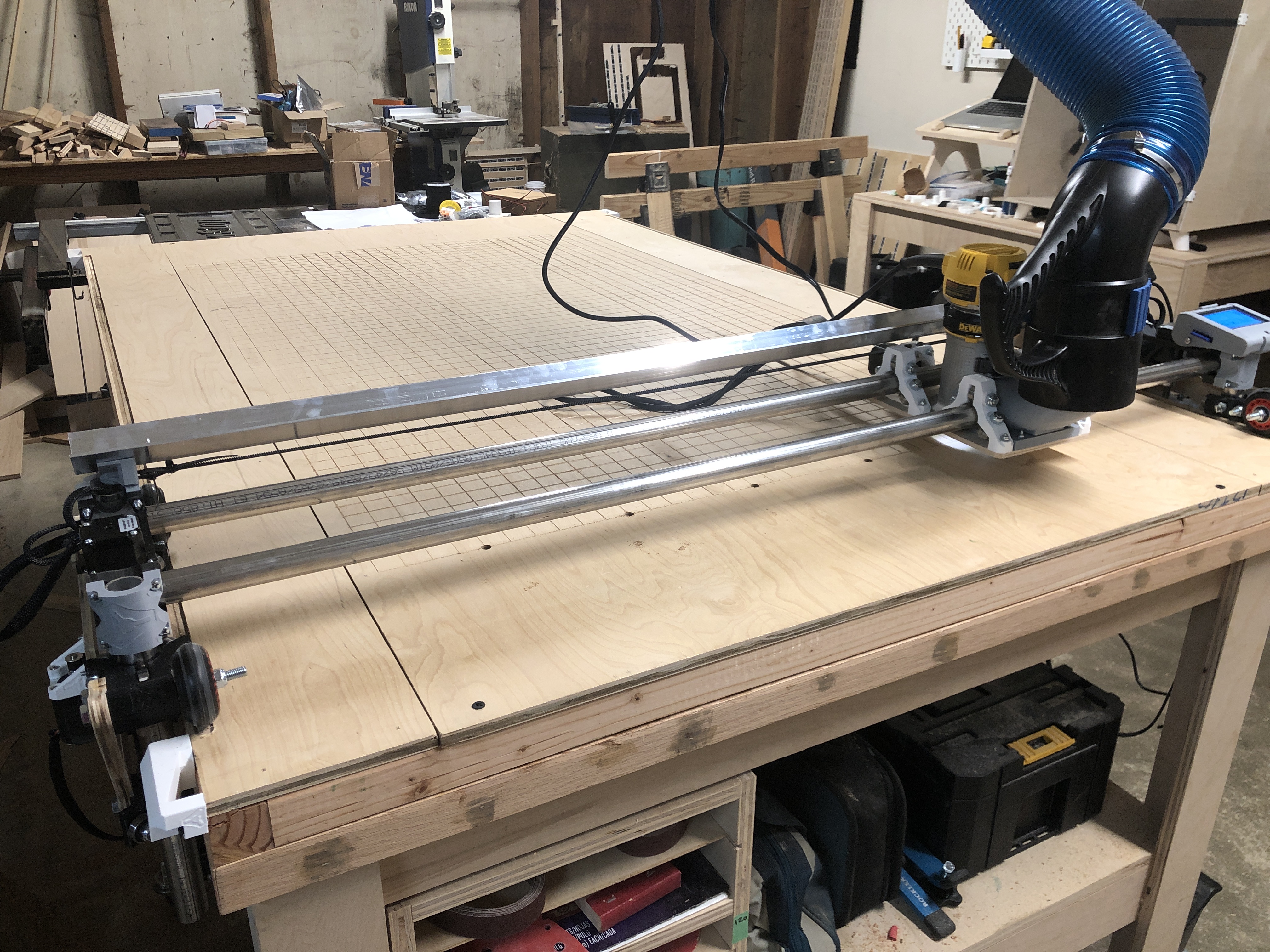
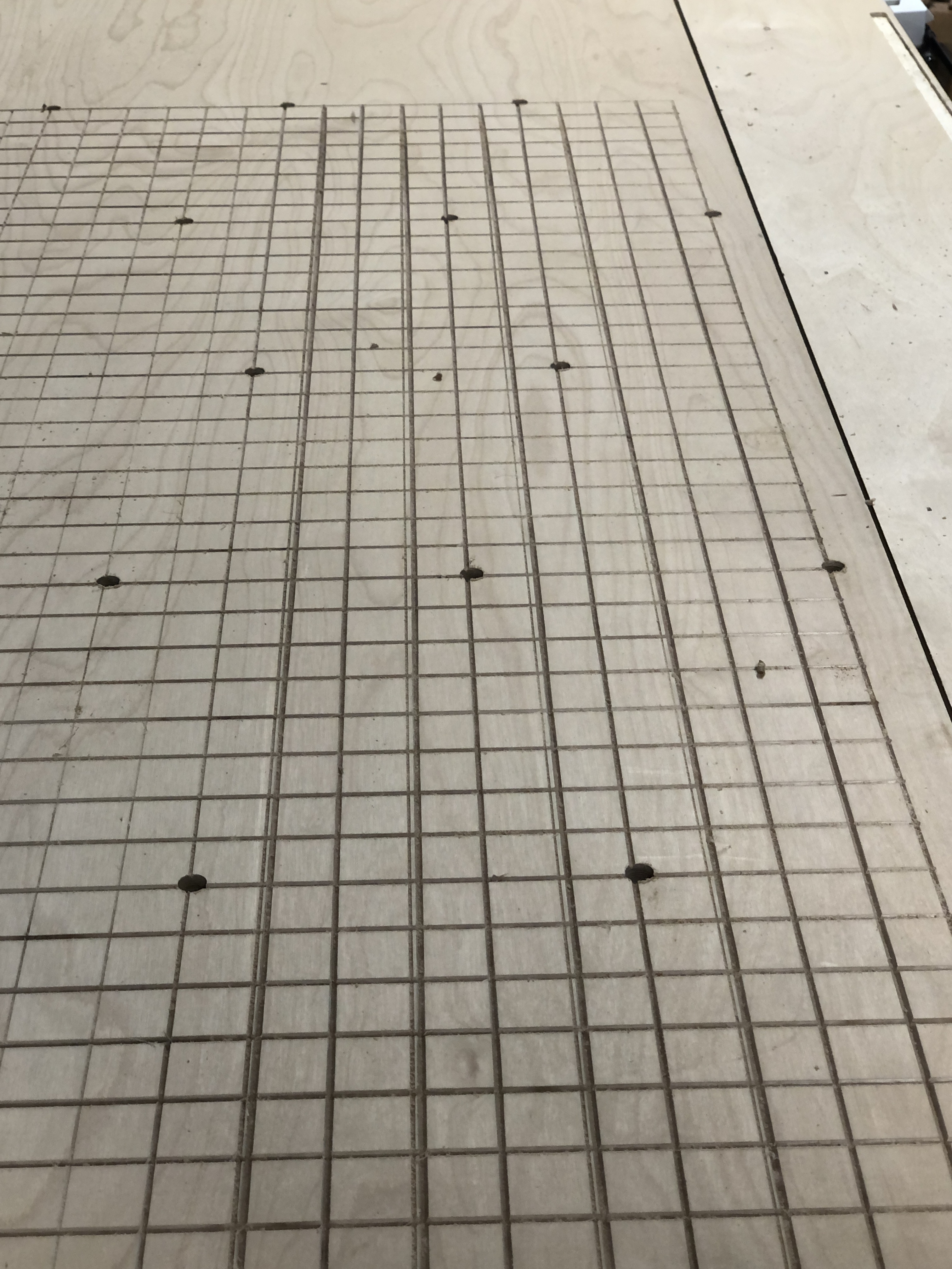
Oh yeah. Those pictures were terrible after looking at them again. I’m amazed at how much people got from looking at them. Here is a much better shot of the setup.
@mordiev - The engraving is centered on the lines using a trace tool path in fusion.
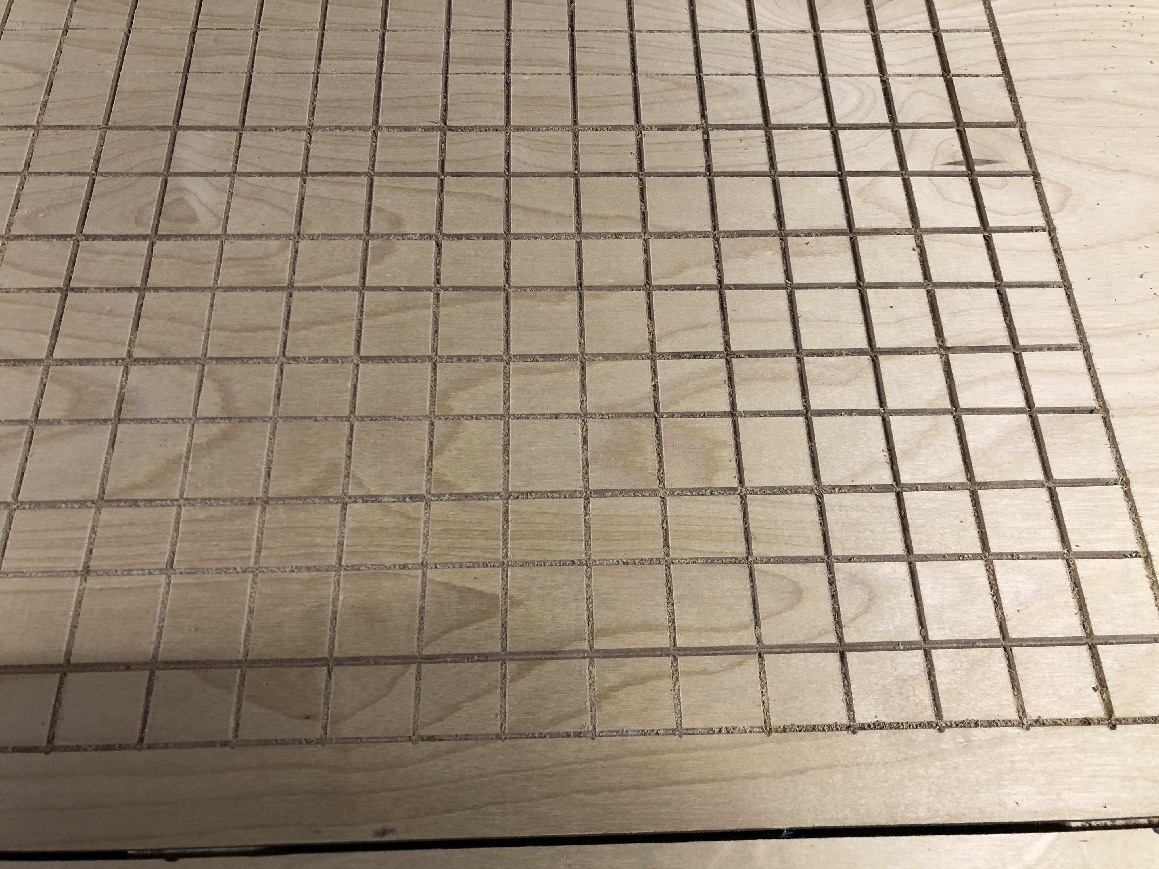
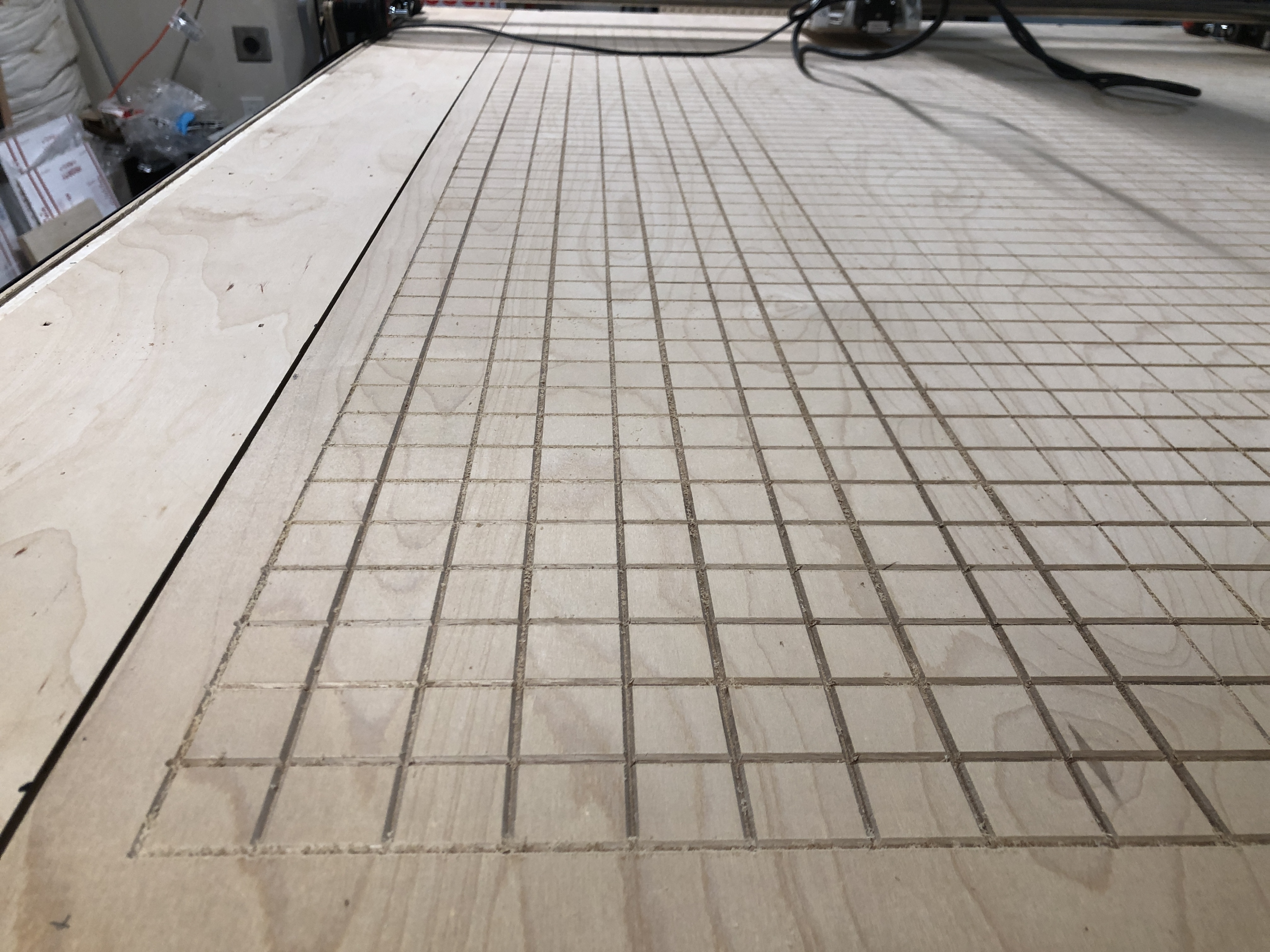
@jeffeb3 - I took some measurements this morning, and yes they are bowing slightly. It’s wider at the ends and seems to veer towards the outside edge in the middle.
@barry99705 - They are supposed to be the same depth, but I believe there are variations due to the table not being completely flat. I also adjusted the depth on the 611 mid way through since it was cutting so deep.
The cut starts on one end and jogs all the way down the table. I then start the next cut from the side of the table the previous cut ended on. I thought it would be ok, but is that bad practice on cuts of this length?
So, because of the rotation of the bit, it may have been pushing to one side.
You should be able to do that, but if you were going too fast, or too deep (on purpose, or because of a slant in the table), it would be pulling the bit over one way, and then the opposite moving the other way. Is it a problem in both directions?
It is hard to tell from here if the settings were too aggressive, or the machine has a problem.
Oh man. I knew that, but I completely forgot about it. I have a feeling that might be the problem since it looks like it was only doing that in one direction. Makes so much more sense now. I think the depth of the bit accentuated the problem. It’s a v-shaped bit, so I don’t know if that is less of a problem or more.
I think it would make it worse. It kind of depends on the shape of the side cutting edge. Some V bits are v shaped, but straight, not spiral. That would make the load a lot higher.
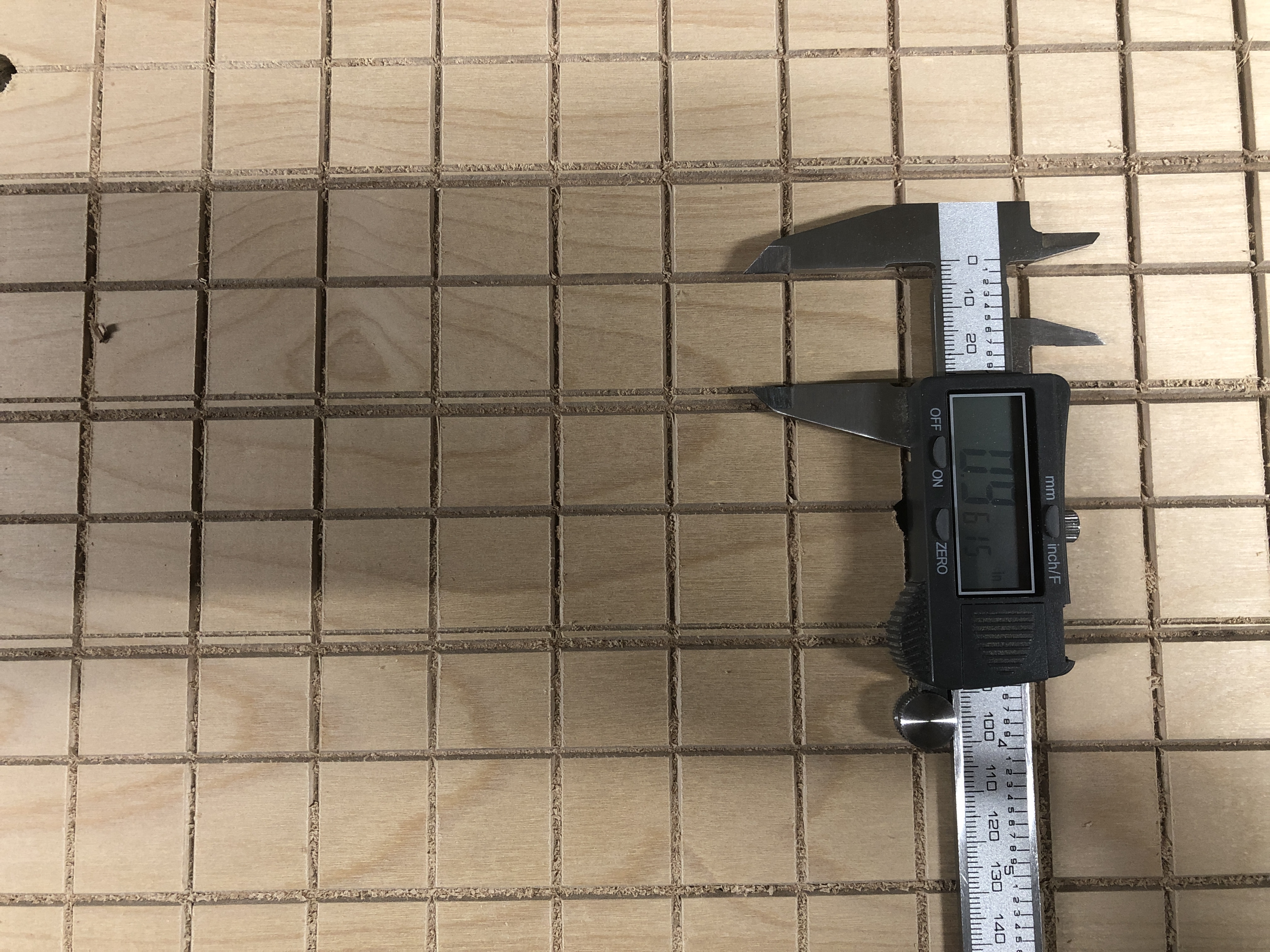
This was the main problem, I believe. There were a few factors I changed, but the one that made the most difference was cutting all the lines in the same direction. I also reduced the feed rate and took a shallower pass. Thanks everyone for your help!
In the picture the thin line is the new one and they all measure the same distance now.
I think that is fine if all you want is the grid, but it’s a workaround for the deflection, not a solution. If you wanted to cut out a circle, you aren’t going to be able to do opposite sides in the same direction and your circle will come out oversize if you go clockwise and undersize if you go counter-clockwise. Some deflection is normal and it’s just a matter of degree. Slower and shallower is bound to deflect less, at the cost of time and tool life. I can’t say 100% that your machine should be stiffer than it is but it does appear that your machine was showing different stiffness in X and Y, which suggests a problem. That is good news because it means you can improve stiffness if you’re not at the limit of what the LR2 is generally capable of.