Help with endstops, of how low can you go?

Try going even lighter on the pen pressure. I can see the indent on the paper. That will absolutely cause the mismatch.

I can not find the exact post, but I am sure Barry posted it. At Mrrf we ran a few of these on top of each other even after homing and there are absolutely no flaws whatsoever, MRRF 2019 - #32 by ohbaby This even has the screw heads drawn in with a 0.3mm fine tip felt marker. Incredible detail and absolutely no deviation with several passes, and no indents on the paper.

If you are having the same problem try moving to a different spot on your work surface, there is a flaw somewhere on a rail or your belt is broken. This is not normal at all. Plucked tight belts can break the strands and give a stretched spot, that is the reason we don’t run steel belts, they break and it is hard to find the stretched spot.

2 Likes

Either way, pen or no pen, once I tightened up the belts things got real repeatable. I exaggerated a little, they are not super duper tight, but they are definitely tighter than I have ever run them. I probably only needed to tighten them 2 turns but I went over and did 3 turns. I have needed to tighten at least 6 times since I built the machine. They seem to stretch when ever I crash the trucks which happens sometimes when experimenting or forget something laying on the table.

I think at this point, alignment is no longer an issue. It is aligned as best as visually possible. The offset is 0.59mm, so I actually set it to the 100th of a mm. I could distinguish the diagonals change with a .02mm change in offset with the scales. Those are extreemly predictable no load movements to do this.

I think the next phase is looking at reasons a cut circle varies from the alignment. After I check all the bearings I will try some cuts with a heavier finishing cut to see if I can remove the low spot. I am still convinced cutting a circle and measuring runout is the ultamate test. But it is the very last thing to look at.

On the experiential side, I may have come up with an idea to “auto” align the system. I have a couple high grade string pots I think I could rig up to measure travel. I think I could direct measure the diagonals with it, and with some data collection could actually graph the results. Maybe even map gcode coordinates to actual movement. A lot of possibilities here. As I mentioned in an earlier post, I would really like to square up my machine in under 5 minutes and being able to verify alignment before an important cut would be golden.

That should not happen. I am assuming your belts might have broken. The threads inside are either fiberglass or kevlar, once tensioned they should not really move. I have not touched mine in a long time. The steppers should easily skip steps and cause no harm to the system, I have them at the low end of what is needed in terms of current.

Hopefully you did just start too loose and didn’t break a thread.

Sounds like I may need some new belts. Thanks Ryan for all your help, and thanks everyone for all the great input. I will try to pay it forward.

I believe is you use Jamie’s test ruler generator you will be able to see if your belts are stretched in a single place.

1 Like

NEW PROBLEM. My X1 endstop is triggered at all times. Even when it is unplugged from board. I cannot understand how there could be a closed circuit with no cable connected to board. If I unplug the other endstops they show triggered as expected. I reflashed the board 2X with no change. Any ideas?

Are they not all NC and trigger when open? That means it’s just a bad connection. If you swap plugs at the board you can confirm that.

1 Like

Yup that means your endstop came unplugged or the wire got cut somehow.

They are all NC. I even found that command in the Marlin firmware. They all trigger when open. Except X1_min. It shows triggered (closed) at all times even with no cable/endstops connected. I pulled out the board and all the pins look good and secure.

Did that plug ever get plugged in wrong, if you hit power and signal it will not work any longer. You can swap the pins with Z max if it is burnt out.

Look for the rambo pins file and just swap xmin and Z max numbers.

1 Like

Well that was too easy. BACK ON LINE. Thank you so much for a quick response. Ryan you are awesome.

2 Likes

I spoke too soon. The M119 showed X1 triggered. I plugged back in the endstop switch. Then X1 showed open. All good. I did a home command, all good. I powered down, stuck my board back into the case and reconnected USB. Then power up and X1 is triggered again. Even when disconnected from Zmax.

Check for dirt or something on the board and in the winter static can get ugly make sure everything is grounded well, especially vacuum hoses.

When I put the board back in the case I also plugged back in the cooling fan… I turned off my cooling fan that blows across the board. And it works again???

It is still triggering intermittently

Just found a break in the wire. Sorry for the inconvenience.

2 Likes

Every time the gantry moved it was either breaking or shorting. I got so frustrated I started mixing up my NO’s and NC’s. I kept doing continuity checks and it would pass until I finally moved it the right way… I apologize for not spending more time troubleshooting, I was sure I had a board problem. That was tricky.

Everything back together and squared to under 0.25mm on a 400mm square. Starting cutting 150mm circles in PVC again. The are all within 0.25mm also with no flat spots. I am going to try a few cutting experiments to see if I can find the variation. But I think I can live with that if I need to.

I also verified my auto squaring idea on paper and mechanically. It makes for a cool little DRO for the MPCNC. No separate X/Y, only diagonals. I need to fab/print a mount that fits over the top cap on the leg at origin to hold the string potentiometer and buy a cheap digital readout. Not exactly sure if the resolution is enough, but I have hopes.

3 Likes

No need to apologize. Sometimes it is things you’ve already checked. And the nature of NC is counter intuitive for something so simple. I bet you everyone has made that mistake that understand it.

2 Likes

Results of my final experiments.

After going through the machine, moving the legs to take out some bind, changing the belts, checking bearings, looking for friction and play, I performed a squaring operation using 2 x 24" machinist scales set up in a cross pattern.

I needed to cut some parts in aluminum that will be rotating so at least need to accurately make some centering holes for later drilling that are within .2mm positional tolerance or better So unloaded movement accuracy is priority and cutting a roughly 100mm circle needs to be close to the same but not as critical.

So my thought was to cut some 300mm circles in something that could be rotated and checked for runout. Best thing I could find was 1/2" thick pvc sheet. It gave a relatively smooth cut finish that I could hit with some 220 sandpaper and get a good measurement. Then I realized 300mm was not cost effective so I switched to 150mm circles. This should give a good indication of machine+cut+flex accuracy.

My initial cuts as described above were with 1/8" kyrocera single flute endmill at 5mm depth, 100% width at 1400mm/s feed rate. Finish cut full depth with 900 feed. I recognized some variation in the cuts and was still around 0.25mm runout. For my final runs I moved to a 2mm cut depth and 1800 feed. This took additional load off the machine and reduced the variation.

I

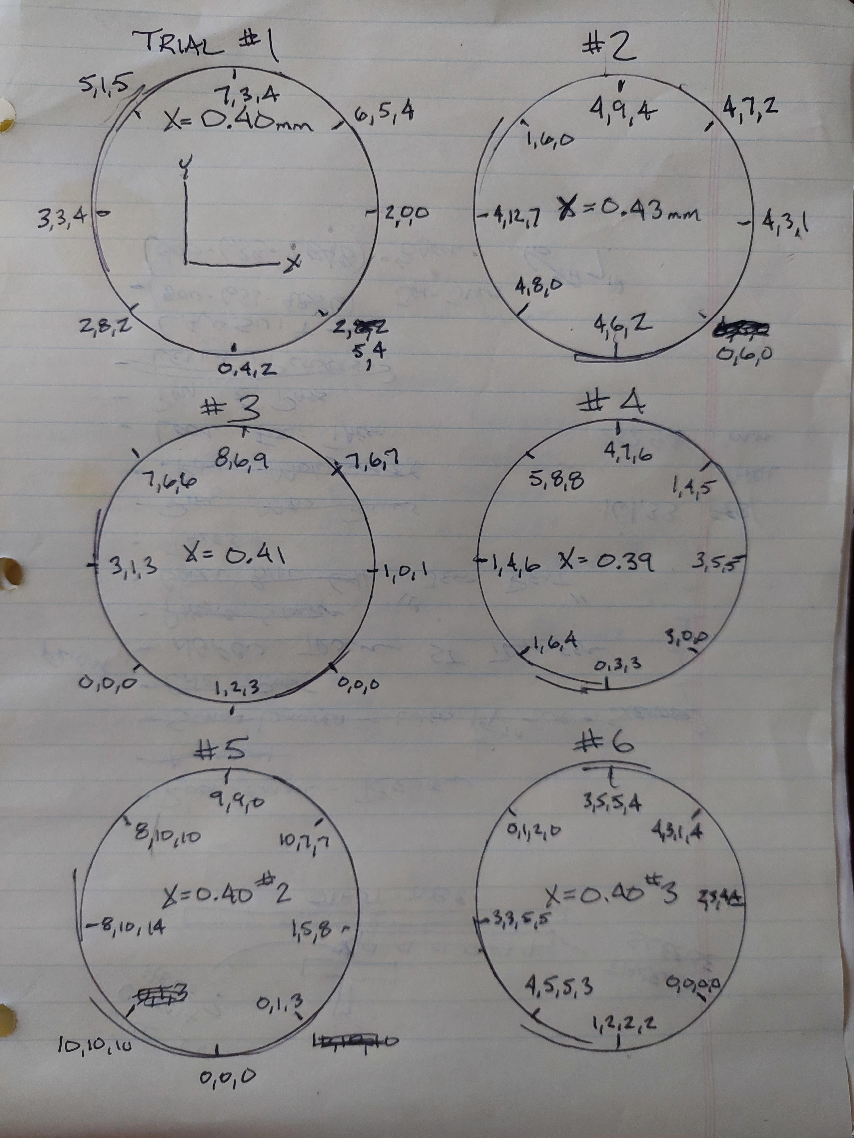
Trial #1- My programmed offset is X=0.40mm. Trial #1 is with that offset. I found that depending on where you measure runout on the .5" cylinder, you can get a slightly different result so I began taking 3 readings. All are in thousands of an inch (2=0.002").

Trial #2- programmed offset X=0.43mm. This resulted in some higher numbers in the diagonal from origin so I thought I went too far.

Trial #3 - X = 0.41mm, this definite shows some higher numbers on top half of circle. Not sure what that means but they were worse than Trial 1.

Trial #4- X=0.39mm. This was no better than Trial 1 either and looks like the top left to lower right might have gained.

Trial #5 - repeat ot Trial #1, X=0.4mm. Definite higher numbers than Trial #1 most of circumference. Since the original numbers were not repeated I began searching for play in bearings. I tightened up the core bearings where I found just a little movement.

Trial #6 repeat trial 1 and 5, X = 0.40mm. Equal to or better than Trial #1. Max out of round is 0.005". Most consistent results on different levels of cylinder. I took 4 reading here.

Summary
1 Accuracy and repeatability unloaded is extreemly good, better than I can measure.
2 Accuracy and repeatability when cutting depends on tool loading. If you need accuracy, you want to run the lightest tool loads you can stand.
3 machine needs to be in tip top shape. I have mentioned this before. Lock the motors, grab the core and try to move it. There should be no rocking of any kind, just a gradual stiff spring like movement as you press harder. In all x/y directions.
4 cutting circles is no better than squaring with scales. If you are truly worried you cuts are moving after checking over the machine, then you can cut some to verify. Measurement variation can be up to 0.003" on my small circles. A larger circle would obviously be better and more representative. I don’t know of a cheap material to do this with. I may run another before I start a critical job.
5 I am not sure this will translate to an aluminum cut, but will post results. As long as I can centermark holes for drilling accurately, I will be ok.
6 Best method of squaring machine so far is machinist scales.

Thanks to everyone for the inputs. I hope this helps the community.

1 Like

Blasting out some 25mm thick 200mm diameter parts used in a rotating assembly. The dims were within measurement error of my trusty Brown and Sharp calipers. But mostly posting to show my proud 25mm deep accumulation of chips. I love it so much I don’t want to vacuum to bed.

7 Likes