Hi,
I want to carve a simple airfoil for a plane. I have the 2D shape, but can’t find software to extrude this into an actual airfoil. I am assuming that once I have this 3D shape, Estlcam will be able to produce the gcode to carve it?
I’ve looked at vCarve, and at Carveco - both WAY too expensive for what I need. All I want to do is this one simple thing: produce a 3D wing from a 2D drawing, and get Estlcam to do the rest.
You have the profile? Aren’t most wings more than just an extrusion of a 2D shape?
If it is just extruding that shape, it should be easy to convert to a 3D shape and export as an stl.
In onshape, I would:
new sketch, click the right plane.
import the dxf (there is a dxf button). Paste the foio somewhere.
hit the checkmark to close the sketch
push the extrude button. Click inside the part I want extruded
choose the length of the extrusion, click the checkmark
find the part in the part list on the bottom left, right click, export, choose stl.
Then you can import that in estlcam and start cutting away. There will be a bunch to learn about the carving operation too. I think almost any cad program (fusion, freecad, sketchup) will have a similar process
Fusion 360 has a free/personal version that can extrude a shape from a 2D profile. If you provide me the 2D shape and a length, I’d be glad to provide you a STL file of the airfoil.
Hi,
Excellent. Chord = 120mm diminishing to 80mm, over a length of 1350mm
This is actually for a wing strut. I plan to carve this out of a piece of Spruce - first one side, then flip the wood over, and then do the other side.
When the cord (distance from front to back) gets smaller, does the height also shrink? How does it align? Is the midpoint the same? The trailing edge a straight line?
To do that in cad, I would need to make another plane (not a flying one, the geometry one), offset by 1350mm, and scale the shape. Then I would do a loft (I think that is the right name) between those two shapes and it would connect the patterns in a 3D shape.
Here is ZIP file containing the STL file along with a Fusion 360 file used to generate the wing. I aligned the bottom and the trailing edge between the two profiles. This may not be what you want. As Jeff says, you are missing the information on how the two profiles are aligned. The process I used to make it:
Import the image as a canvas
Align the back edge with the origin and scale the canvas to match the 120mm specified
Create a sketch and use sketching tools to create a closed profile of the wing.
Create an offset plane 1350 mm away and create a sketch on that plane
Paste a copy of the first profile and resize it to 80mm relative to the origin
Use a Loft to create a 3D model between the two profiles
Export the STL
If you want the two profiles aligned differently, let me know. The easiest way would be to include a point on the image of where you want the two to align. Note that most CAD programs save the history of the steps used to produce an object. You can go back and edit any step, and the changes will percolate through the design so that you can make changes without redoing the whole design. The learning curve for Fusion 360 can be steep, but you could download a copy of Fusion 360 and play with the design I’ve provided if you like.
Hi Jeff,
First, thank you for taking an interest in this, and I apologise for taking for granted details you couldn’t know.
As the chord gets smaller, the airfoil is just scaled down. Any number of the scenarios you suggest are possible, of course, but probably the most useful would be with highest points (the 40% point) aligning, and both ends flat on the same plane.
I haven’t had a chance to check out Robert’s ZIP file yet, or to try to replicate his method (we sleep here in OZ while you guys are beavering away…)
Regards,
Duncan
Hi Robert,
This is fascinating stuff. I’ve been threatening to learn a “proper” CAD program for ages, but since I have designed (and am not building) an airplane cut entirely out of aircraft grade plywood, Sketchup has served me very well. Except when it comes to things like this. It says it can export as a STL file, but when I open the STL in Estlcam, it is garbage. Also, Sketchup doesn’t do curves - it approximates them with a series of straight lines (as you probably know). Two rather serious drawbacks in work like this. So this might just be the nudge I need.
Right - I’ve make a steaming cup of coffee (it’s getting cold here at the moment), I’m still in my dressing gown at the laptop, and I’m about to follow your instructions.
If you are going to try and change the alignment between profiles, you may want to spend a bit of time on a basic Fusion 360 foundation. The profiles are currently anchored to the origin using a Coincident constraint that must be deleted before the profiles(s) can be moved. Note that the timeline on the bottom of the screen shows the steps I took, and you can double click on any of these steps to edit it.
That is strange. Not sure if the issue is Sketchup or EstlCAM. Some 3D printer slicing software exports/saves STL files, so you might try opening the file in a slicer and then saving it back out. Another thought is MeshMixer. I’ve only occasionally used it, but I believe that it automatically fixes certain kinds of errors, and I know it can save in STL format.
Sketchup eill happily make things completely out of planes and you have to be careful to make it actually make shapes. So it is easy to end up with goofy looking stls. It is also tricky to use for dxfs. It is great for woodworking plans, but not great at being concise enough for CNC machines (including 3D printers). It will work in a pinch though.
…as I’m discovering. But to be fair, it has drawn my plane accurately enough to cut it and everything fits perfectly. For flat stuff, it’s perfectly adequate.
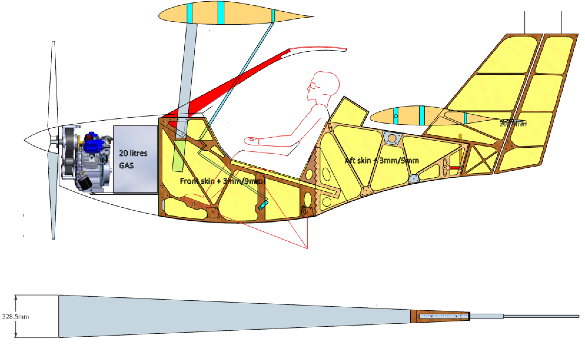
In case you’re interested, here’s the plane, cut out of 15mm ply. I call it a Fleabike because it is a Flying Flea, and as you can see, the pilot straddles the fuselage, just like a bike. So it is a piece of cake to cut on a cnc router.
FWIW, .STL meshes also don’t do curves, they approximate them using a series of straight lines. It’s a limitation of the format. SVGs and DXF drawings can do curves in 2D, but once you export as STL, it re-calculates everything as a mesh of straight lines. Of course enough straight lines, depending on scale, and it might as well be a real curve, but you can usually catch them out in a 3D print of almost anything, if it’s printed in a shiny filament.
I used to use sketchup for shop projects, more to check my dimensions before I broke out the saw, really, but I haven’t used it in a long time, and apparently no longer remember how anything works in it, becase I couldn’t draw a simple 2X4 frame last time I tried it. The UI is completely different now.
Ha ha - snooze you lose. I have the 2018 version, and studiously avoid upgrading. I can operate 2018, the new versions just confuse me. Perhaps it IS time I moved to something more “serious”. I’ve downloaded Fusion360, but I was so confused, I gave up for the morning, and had another cup of tea…
Well, it should say something that the version of Sketchup that I used (successfully) last had Google’s name on it. Pretty sure it was about 2006.
I’m reasonably happy with FreeCAD, slowly learning Open SCAD. I started learning Fusion360, then Autodesk started screwing with the licensing model, and I dropped it. I might give it another go though, since it seems to be a more mature and full-featured product overall.