Thanks for mentioning this!
I was already skeptical on using a plastic version, although mine is only 1000watt, maybe I should spend a little more and go for the metal one.
What is your opinion in size? Would 30 liters be enough, or better double up to 60?
So, just FYI @jeffeb3, you were right about the dog bones effect.
I tried again and this problem is eliminated (but got another instead )
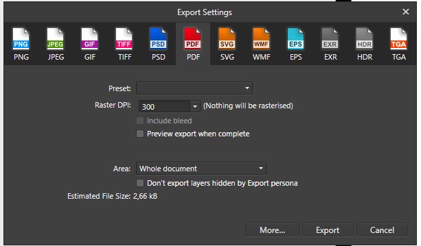
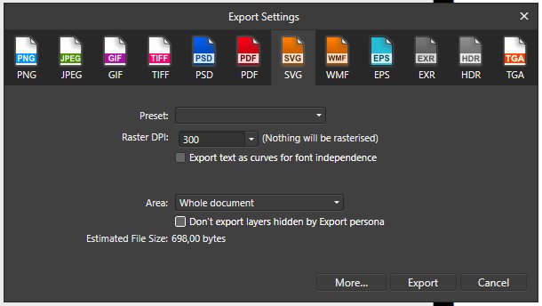
What I did was making a design in Affinty Designer, exported the design to SVG with the option to convert text to path checked on. I opened Photopedea and imported this SVG, and simply re-saved it to dxf.
When opening in Estlcam it imported just fine. Running the job with pocket hole there are no more dog bones.
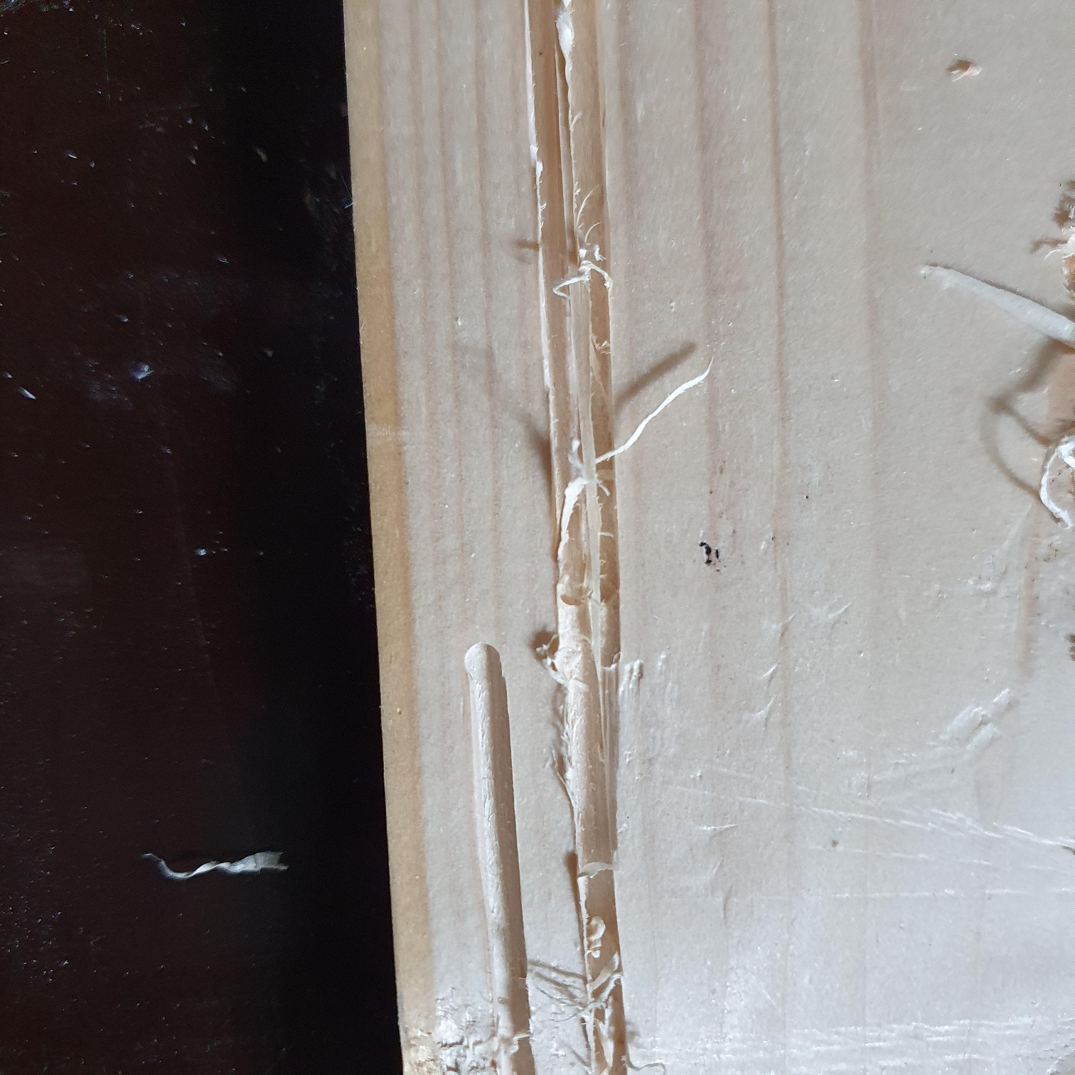
A new strange issue I experienced, is that one letter got much more fatter then designed. I might have made a mistake in Estlcam although the simulation showed exactly my design.
Will post some pictures tomorrow as it’s late and I am getting tired after waiting one hour to see just 3 letters milled :s
So I figured it out, this issue was cause because for some letters I created an island and got confused with inside/outside milling
But I seem to have a workflow issue. Maybe some experienced miller can help me out:P
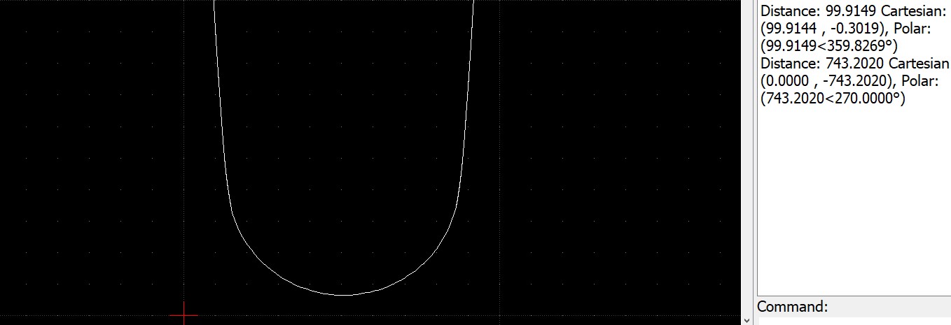
My practical issue is, that my design isn´t keeping its size when milling.
So what I did was;
Create a 1:1 design in Designer 135x1000 (maximum workarea of the wood);
But when starting to mill it came outway bigger (± 150x1400)
I know I should use a CAD tool, but I´m no great artist in CAD and for my simple jobs I expect any designer tool would be enough. But how would one go from 1:1 design to an exact match in Estlcam?
And could it be that there is a bug in Estlcam?
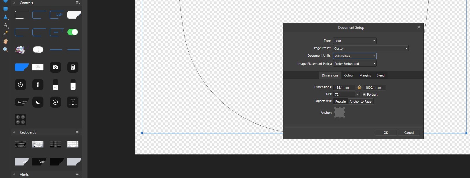
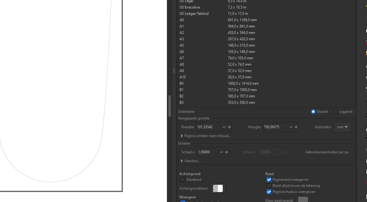
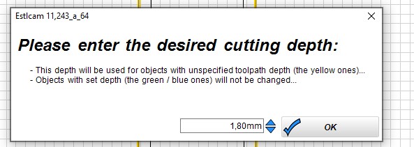
On saving I get the following screen, shouldn´t that be in cm? Like 1,8cm?
With this specific setting, the job only went 5mm in to the workpiece. Making me go complete nuts and confused
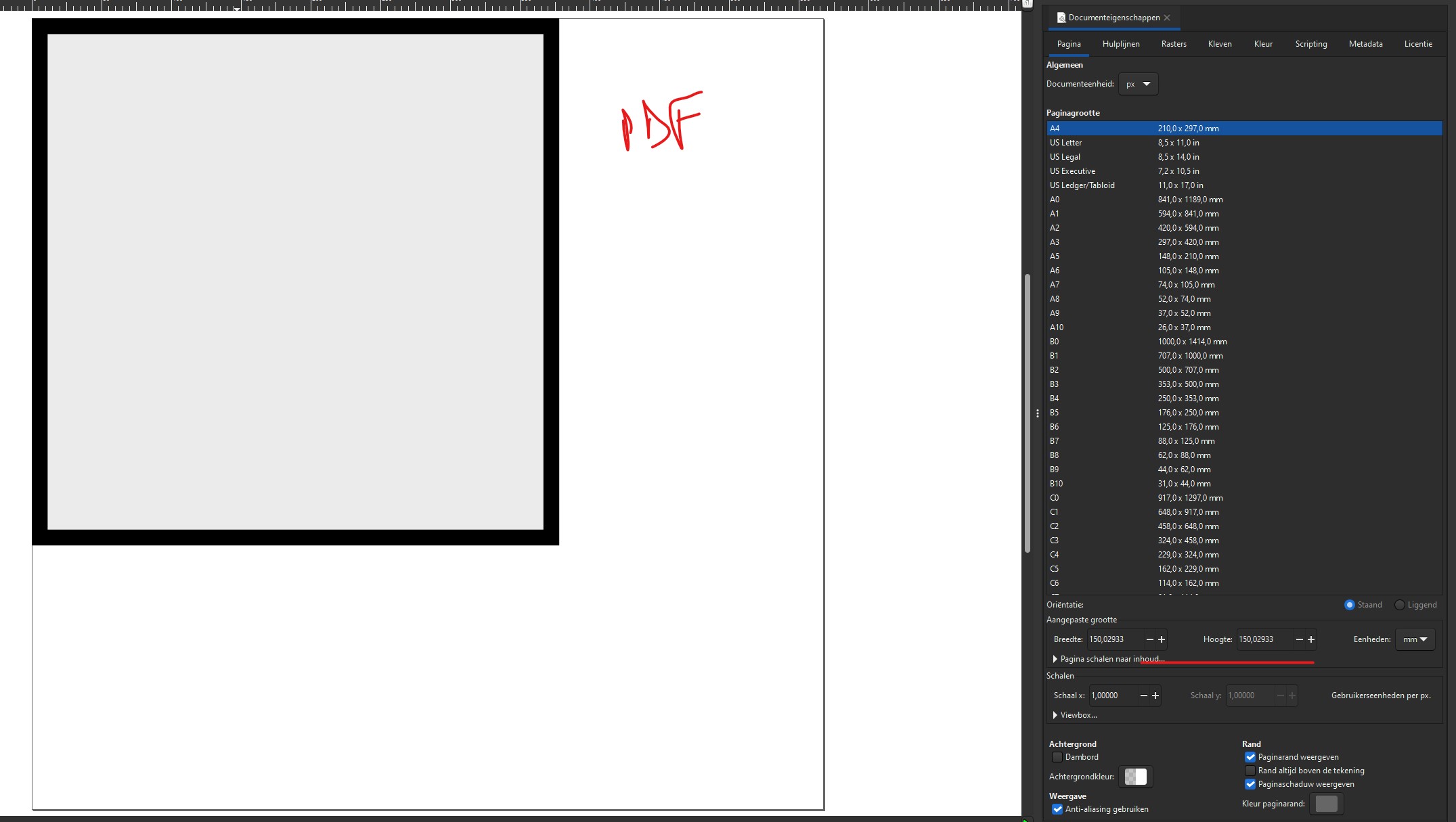
I am not really sure but I remember a few having issues. I think it has to do with your DPI settings.
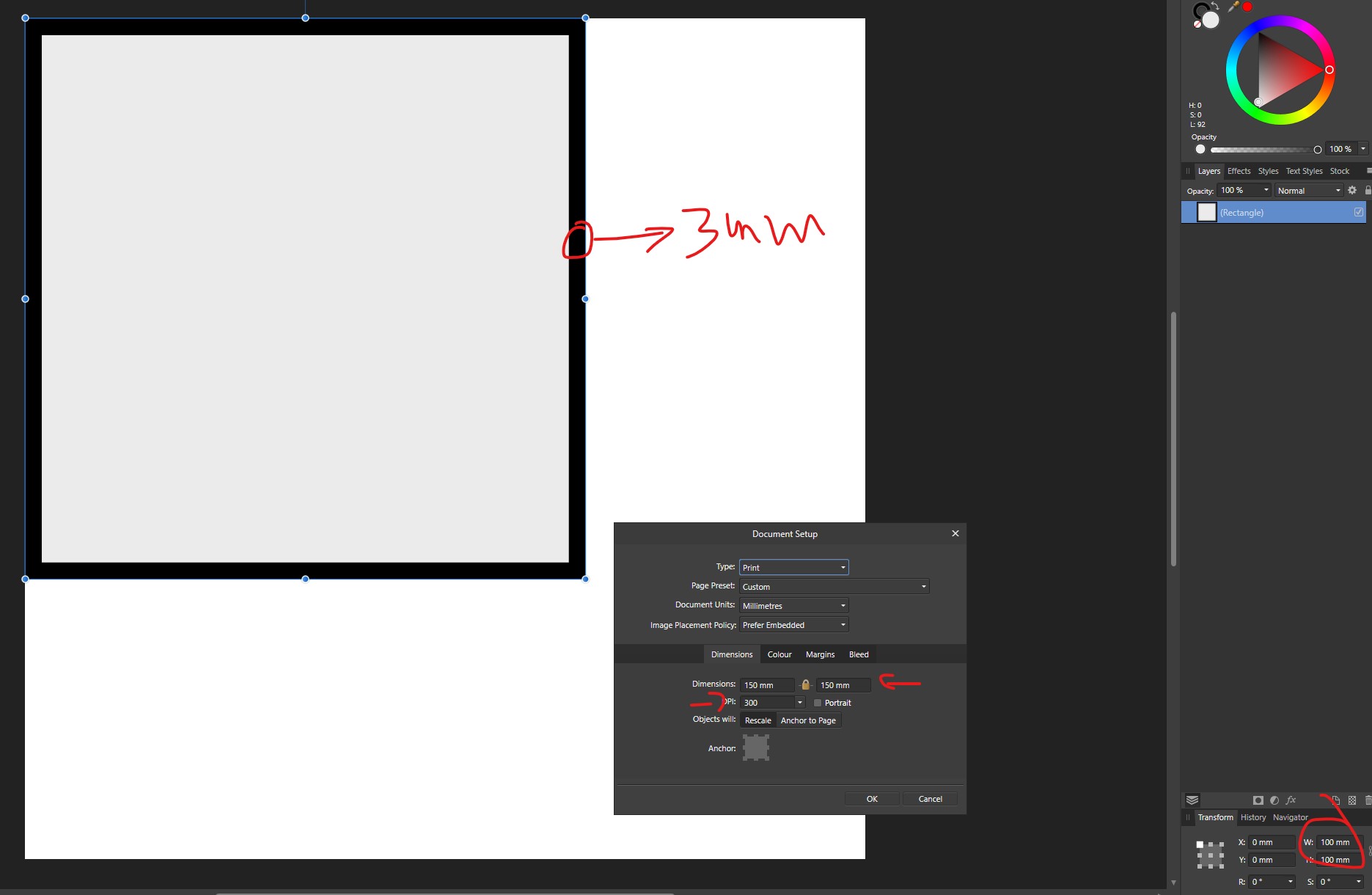
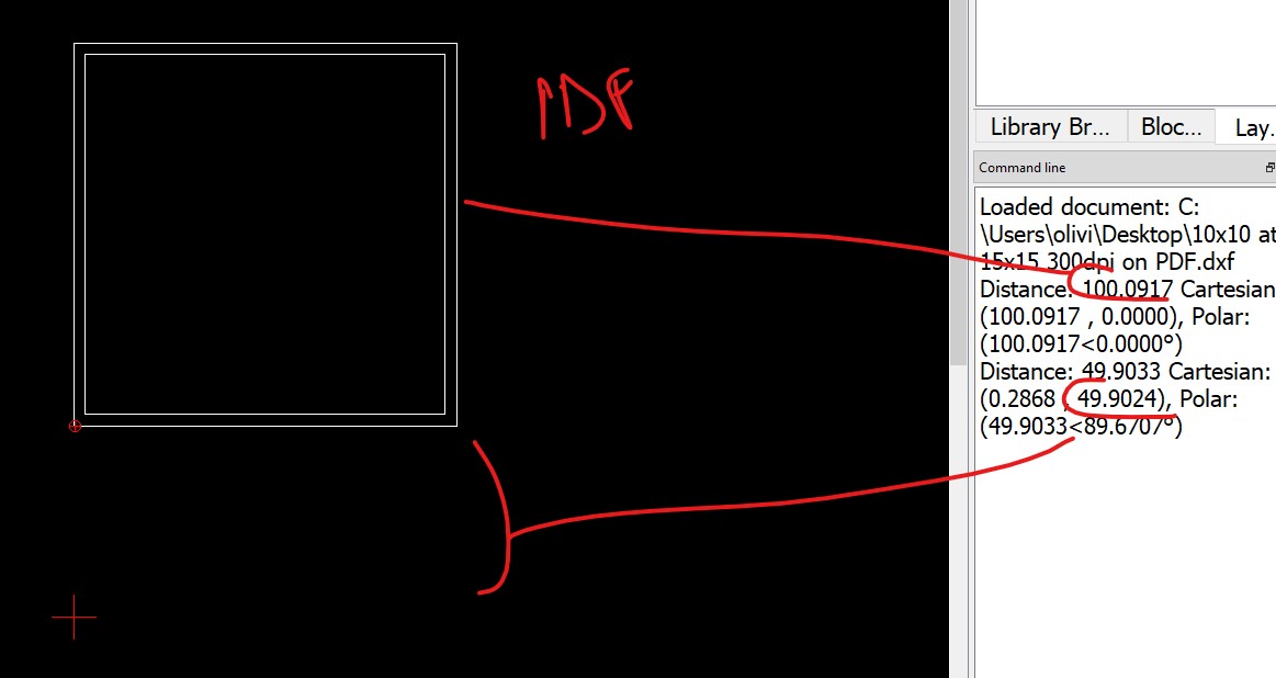
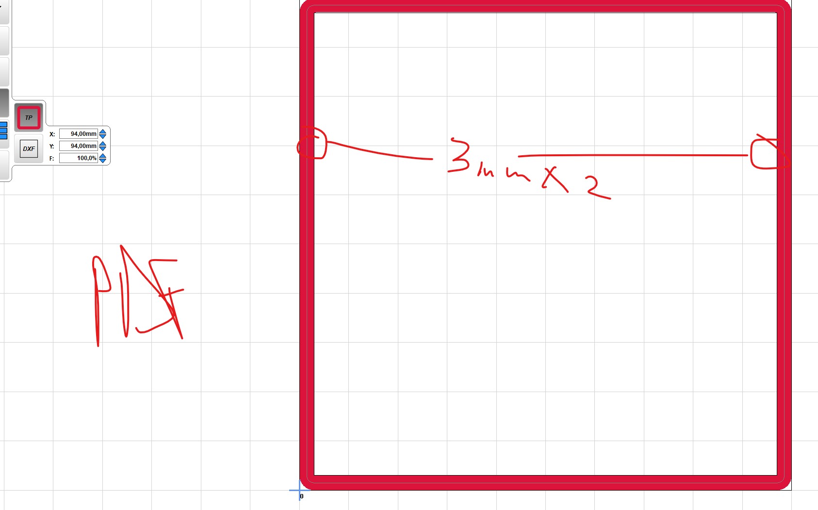
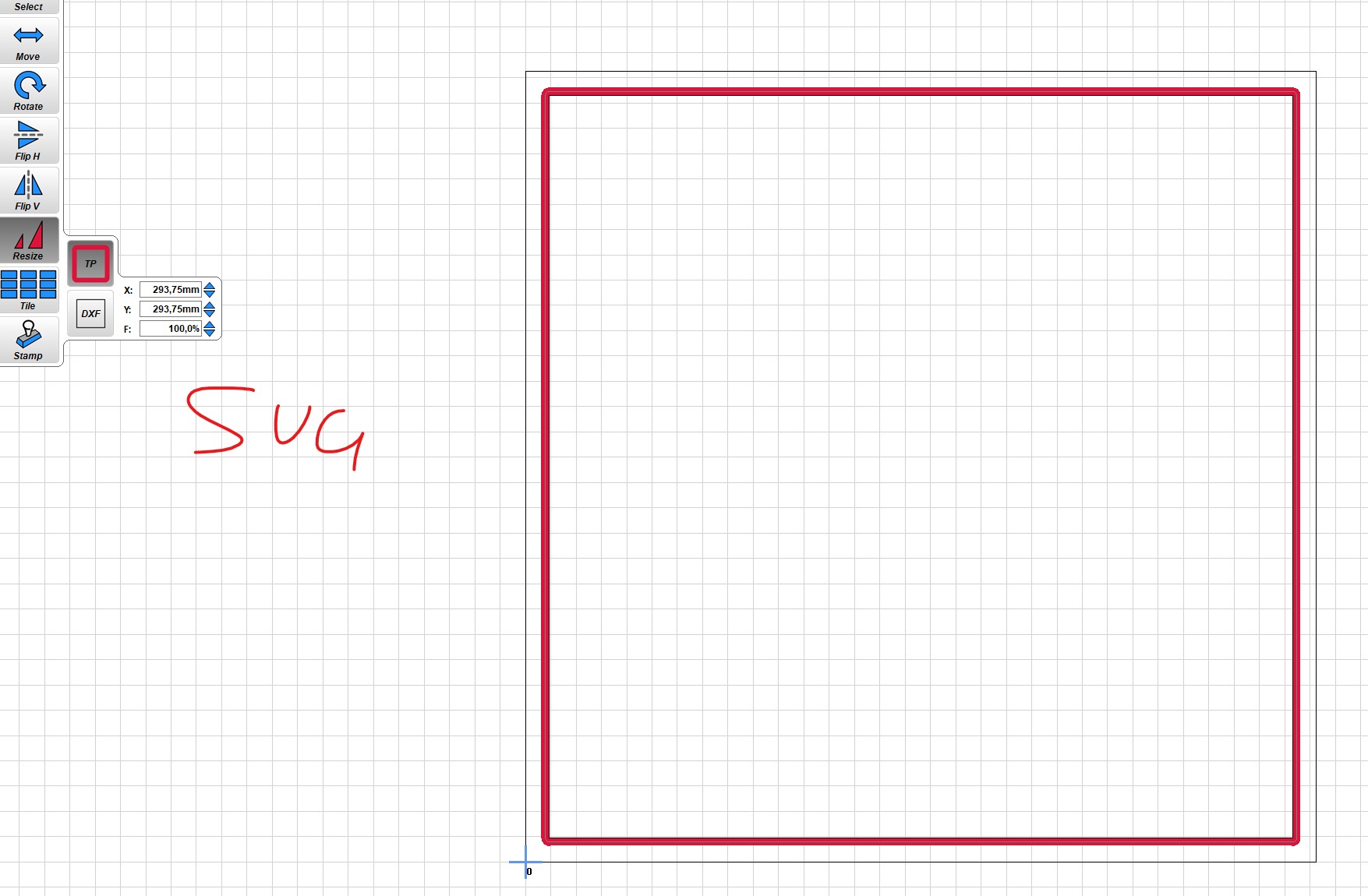
An really easy way to experiment is make a 100mmx100mm box export your SVG and set your estlcam grid to 100x100. You will easily be able to adjust the dpi (I think) to get it right. Yours shows 72dpi, for some reason I know inkscape changed at one point from that to 92 or 96 and it was an issue.
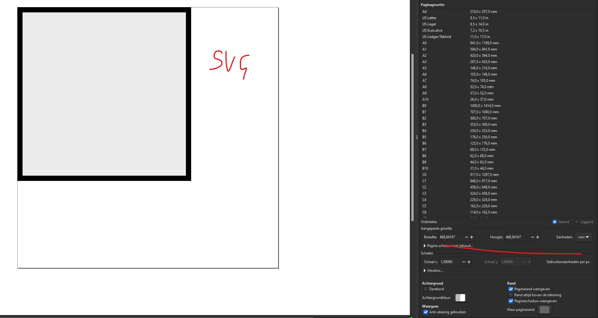
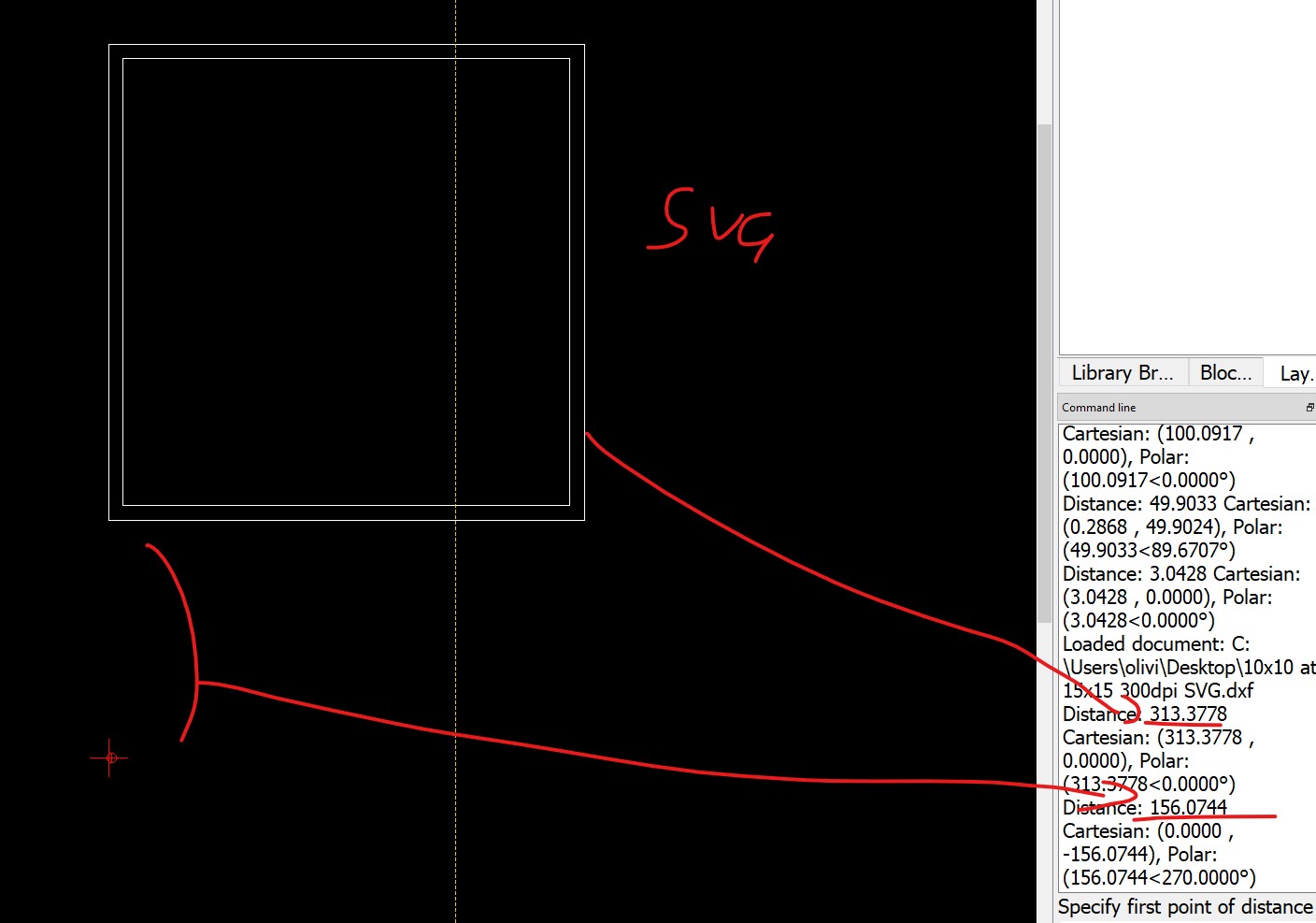
Conclusion is that Inkscape messes up the SVG file.
Also important to note, is that one need to stroke on the correct side of the lines, take into account the bit thickness, and the fact that the offset in the original design gets lost during export to dxf (no idea if that´s always the case).
My lesson learned is either stop using SVG, of use a CAD program, or search another tool then Inkscape.
You need to change stokes to paths, you are going to confuse the heck out of yourself trying to keep track off offsets and finishing passes, changing bit sizes.
But really at this point you have proven you easily have the computer experience to learn CAD quickly, you are easily doing all the 2D stuff as it is.
FWIW
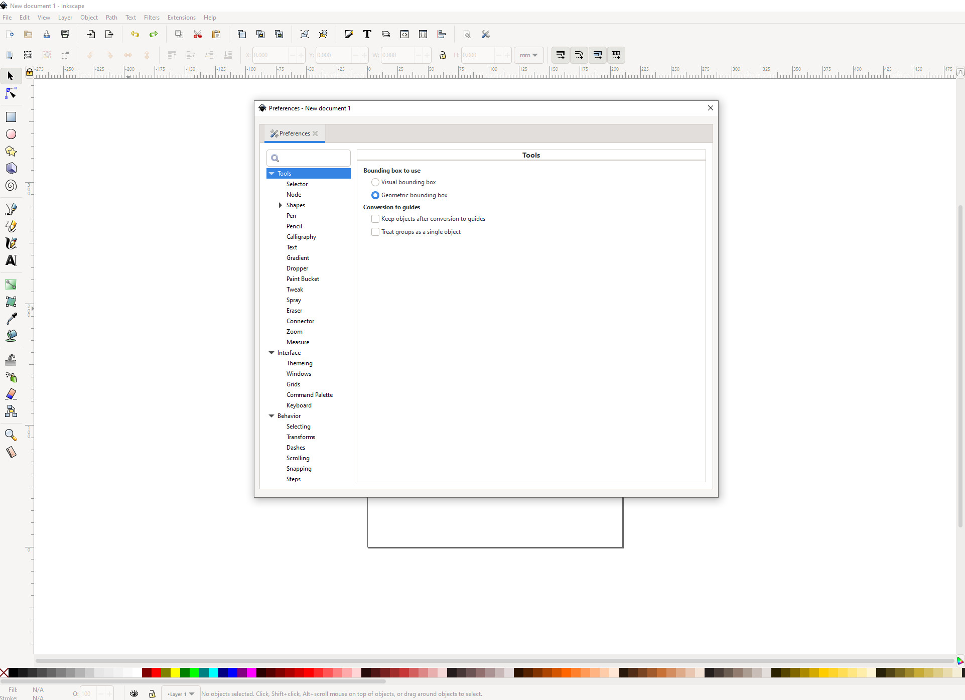
The first setting I change in Inkscape is:
Preferences → Tools → “Bounding Box to use” = “Geometric Bounding box”
This makes it so that the width of the stroke doesn’t impact the sizing of the object. Otherwise the stroke changes the exported and measured size.
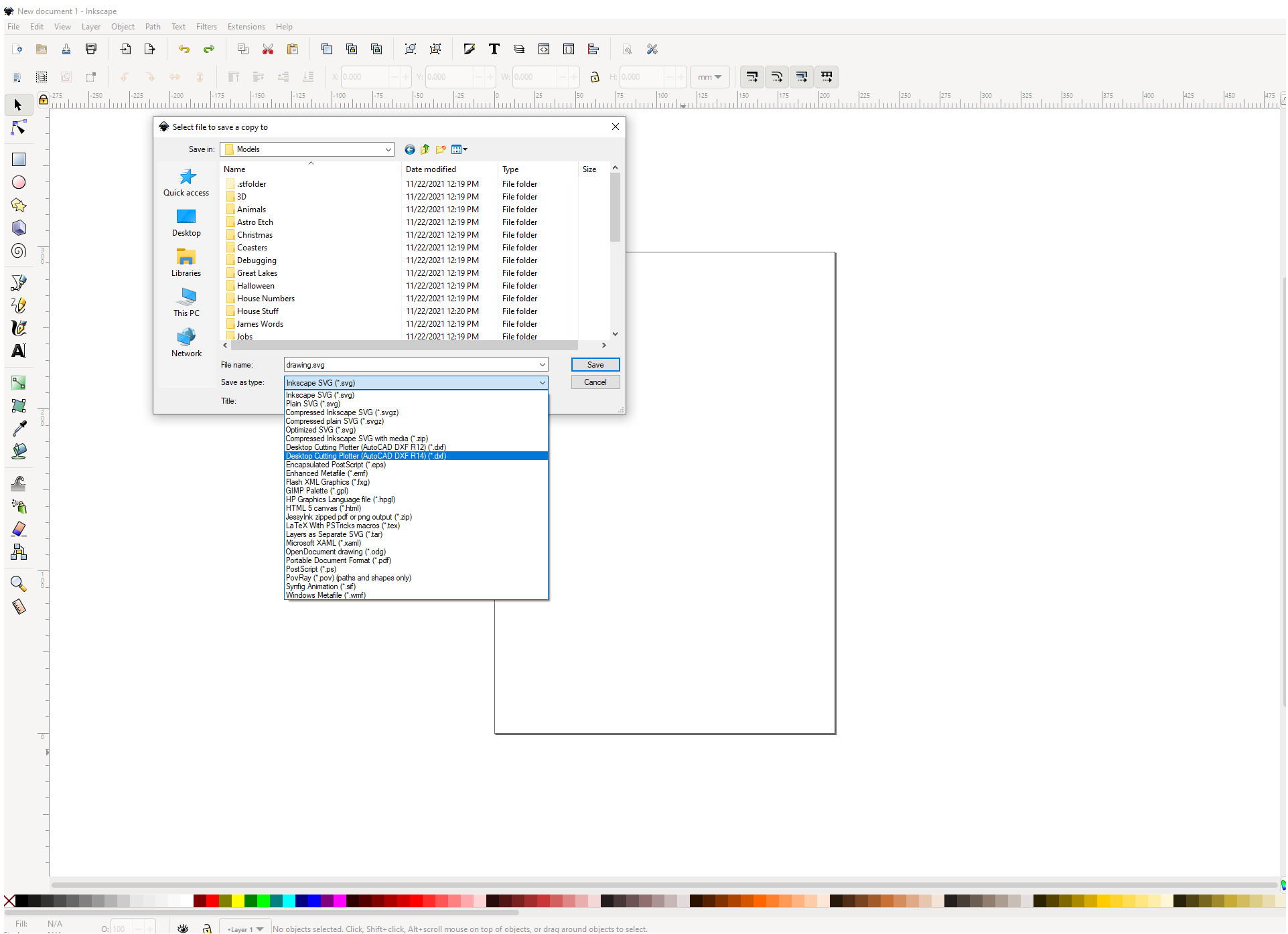
Then…I always save a copy of my file as a dxf to use in Estlcam. svg’s haven’t been reliable but dxf’s seem rock solid (make sure you convert objects to paths though).
Thanks for this thread - it’s about half an hour in front of where I am, and all this talk of svg and paths is a bit frightening! In a week or three we will see how much I think I’ve learned from it!
I am wondering if I actually need Inkscape? I am reasonably proficient in OnShape, and if I use Kiri-moto perhaps I can just get them to talk to one another? That will be an issue if I want to use graphics or lettering I suppose, as OnShape doesn’t really do that simply.
Thanks for the kind words.
Tbh I’ve worked few times with CAD in the past, but for some reason I find those programs counterintuitive. I rarely find the function I need, and the damn thing never seems to want to do what I want it to do even when I am watching tutorials:D
It’s probably me, more used to photo/designer/publisher software, and most of all: my limited patience:) But… I installed Fusion 360(?) yesterday. Let’s see what happens next
Thanks for the suggestion Darwin, tbh I wasn’t planning on using Inkscape, but in an effort to find the reason why my dxf wasn’t properly scaled, I figured to give it a try to convert my files.
Must say that Inkscape improved in the 5 years since I’ve last used it.
So I am going to follow your advice and play with it.
Don’t worry Peter, I am sure you’ll manage it!
No not at all, from what I can read Onshape can export flat files to dxf.
I am taking the long path here because my CAD skills are lacking, and I wanted to start using the machine so it no longer collects dust from standing still
It is one tool, but only one, and if you’re familiar with OnShape, enough to do what you want for drawing in it, then you probably don’t need a different tool.
I’ve used InkScape to convert PNG/JPG files to SVG for stuff, but most of the time, I get lost enough in Inkscape to just close it without actually getting anything done. (I might have to go through some sort of primer to use it at some point.) The only thing that I’ve managed is to convert some files, but not creating my own.
FreeCAD has been pretty good for 2D, and not bad for 3D, so I use that, and it works well enough for everything that I’ve wanted to make
haha, user preferences I got triggered by your post to boot up FreeCAD once more, yesterday evening, got lost in it. Didn´t manage to do anything so I decided to stop trying
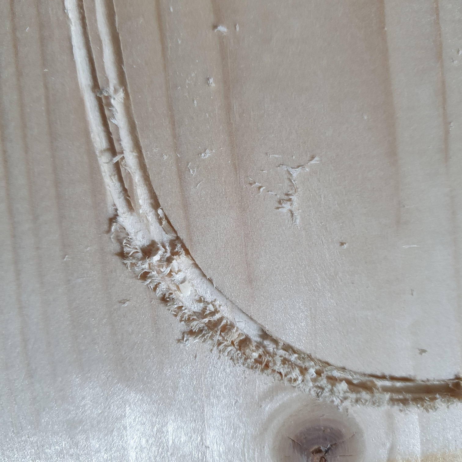
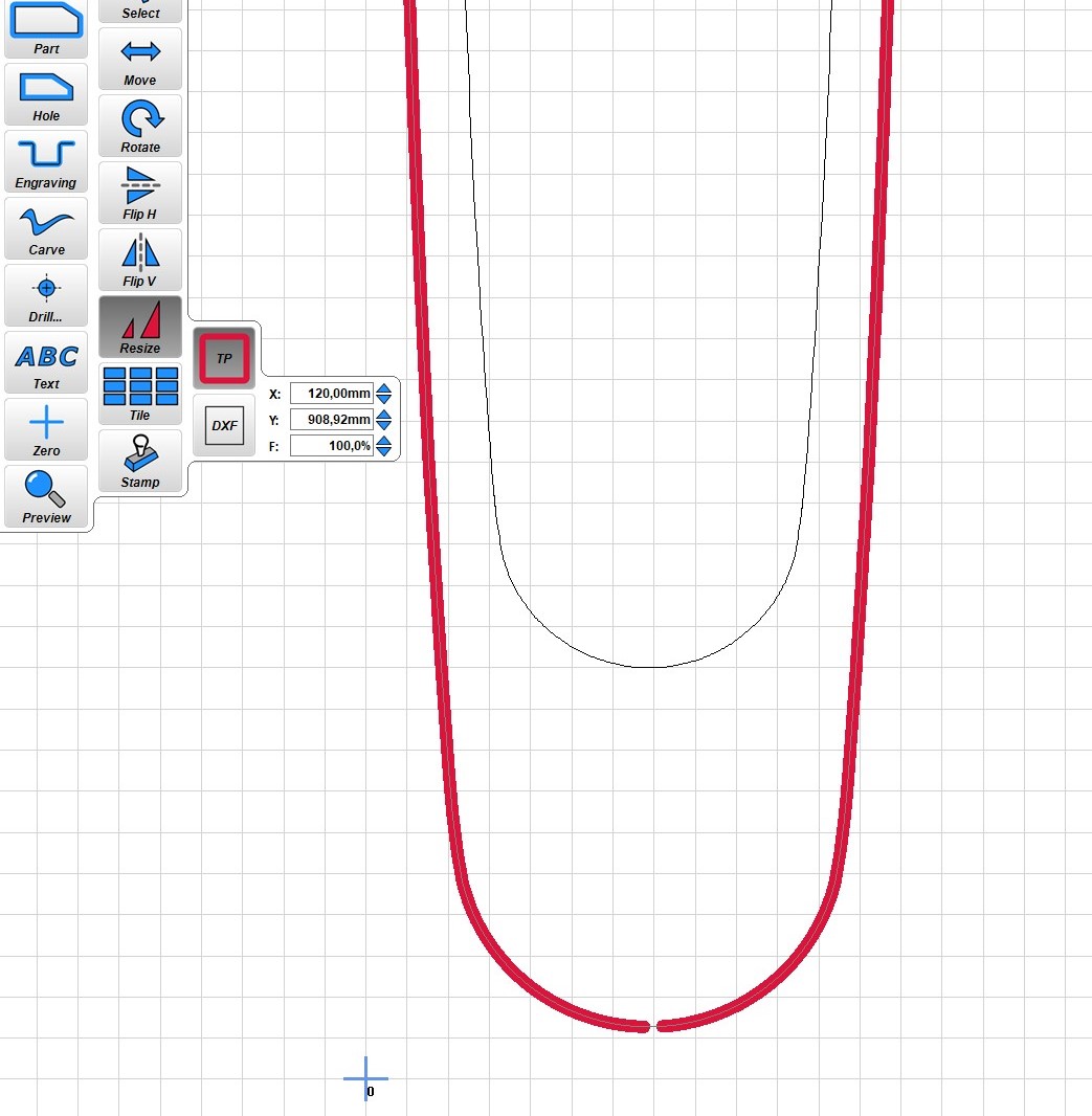
So, I know I had it coming, but this happened while trying to mill a larger oval shape of approx. 1000mm;
My machine seems not to be square. I got away with it milling some text, but for the job I intend to use it, it´s not okay.
I experience 2 issues. Most likely related;
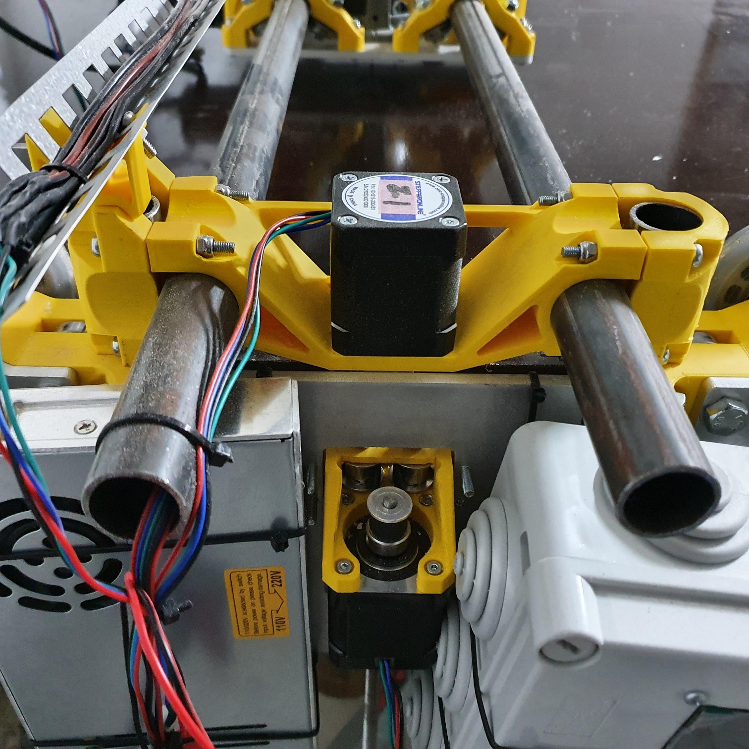
My machine seems to travel sideways. At first I thought it came because the wheels don´t have enough traction on the board. But I think my 3D prints aren´t square;
I´ve tried to change pressure on the tubes on the XY part, but I can´t get it square. If I loosen the screws to much, the tubes just drop to the ground. If I tighten I hear some cracking noise in the parts. So that´s no option either.
I´ve read someone in the forum used tape on the tubes to get it squared. But I can not figure out where to place them to solve my issue. Does anyone have an suggestions on this?
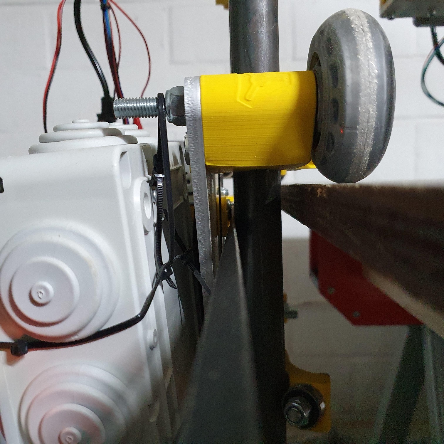
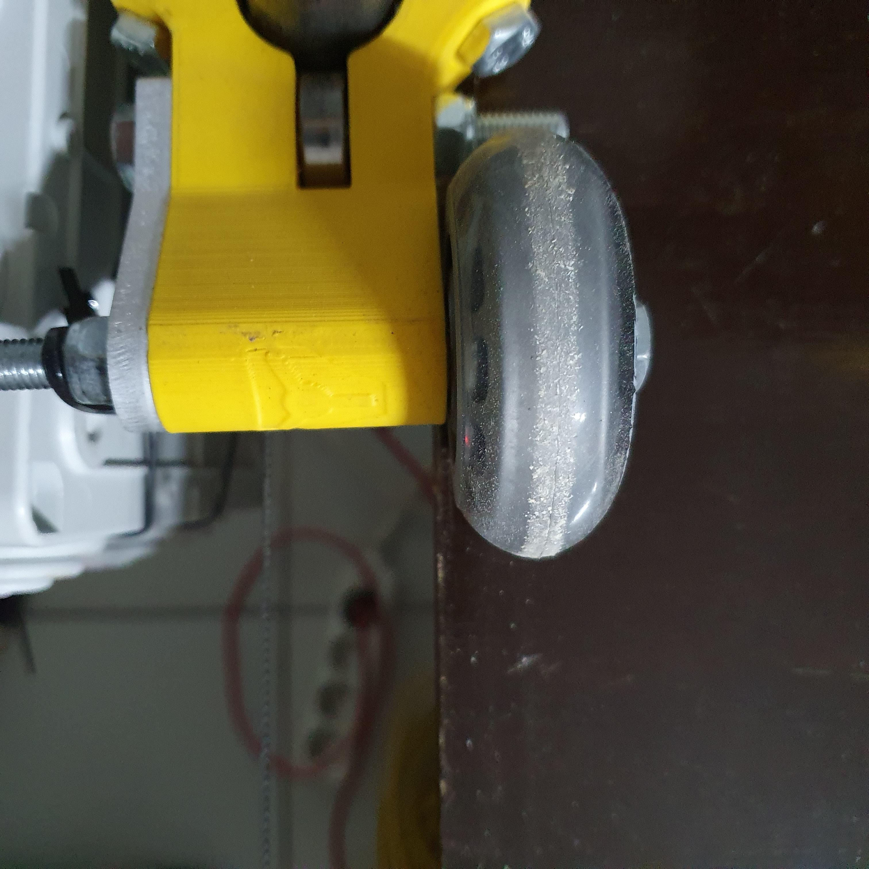
Another thing I notice, is that I have no idea how far the wheels should be from the edge. I read the FAQ multiple times now, but I seem to miss an indication for this distance.
Basically, the track is that the belt is as straight as possible going past the tubes to the idler pulleys. At least that’s what I used as a guideline. The belts are connected to the holders, and go from the holder to the idler, then over tot he motor pulley, then the other idler, and the far holder. I lined stuff up and tightened my X tubes when I could sight down the belt from one holder to the opposite side, and the belt was as straight as possible by sight. This leaves a very small gap between the table edge and the Z tubes.
I put a washer between the printed parts and the wheels, which increases the space a little, but as long as the wheel spins freely, probably isn’t important.
This may not be possible with your setup but a lot of people end up setting up some type of track for the wheels to run in. It helps stabilize the x drift when the machine is moving longer stretches in Y. My version is in the link below, along with my solution to the squaring.
Well, I thought it was fine too based on my observations, but reading your input on the small gap, I might try to bring them closer to the table - so close they just don´t touch. It might improve my issue of going sideways, but probably not enough to run square.
I am sure it is possible to do, however, to find a piece of wood in my area that´s straight - that´s going to be a challenge.
I was already looking to add some linair rail as a solution, but I suspect that even then I would need to get my tubes straigth. No?
Far more important that the belts are straight. The 2 belt segments from holder to idler pulley should form a straight line. If there is any difference in angle of these 2 segments, it will cause linearity issues that are impossible to address in firmware or gcode
I think you’re right. I found that not having a parking spot that was square compounded the problem. So linear rails and a squared stop block on the “bottom” end of the table that I could manually reset against helped a lot.
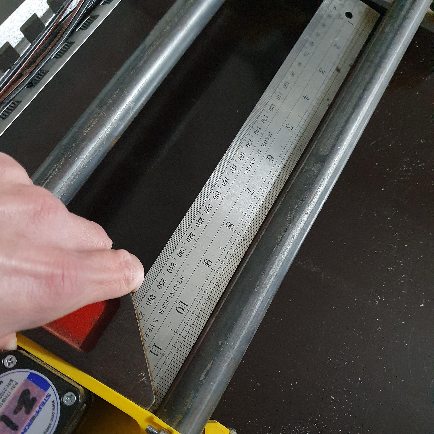
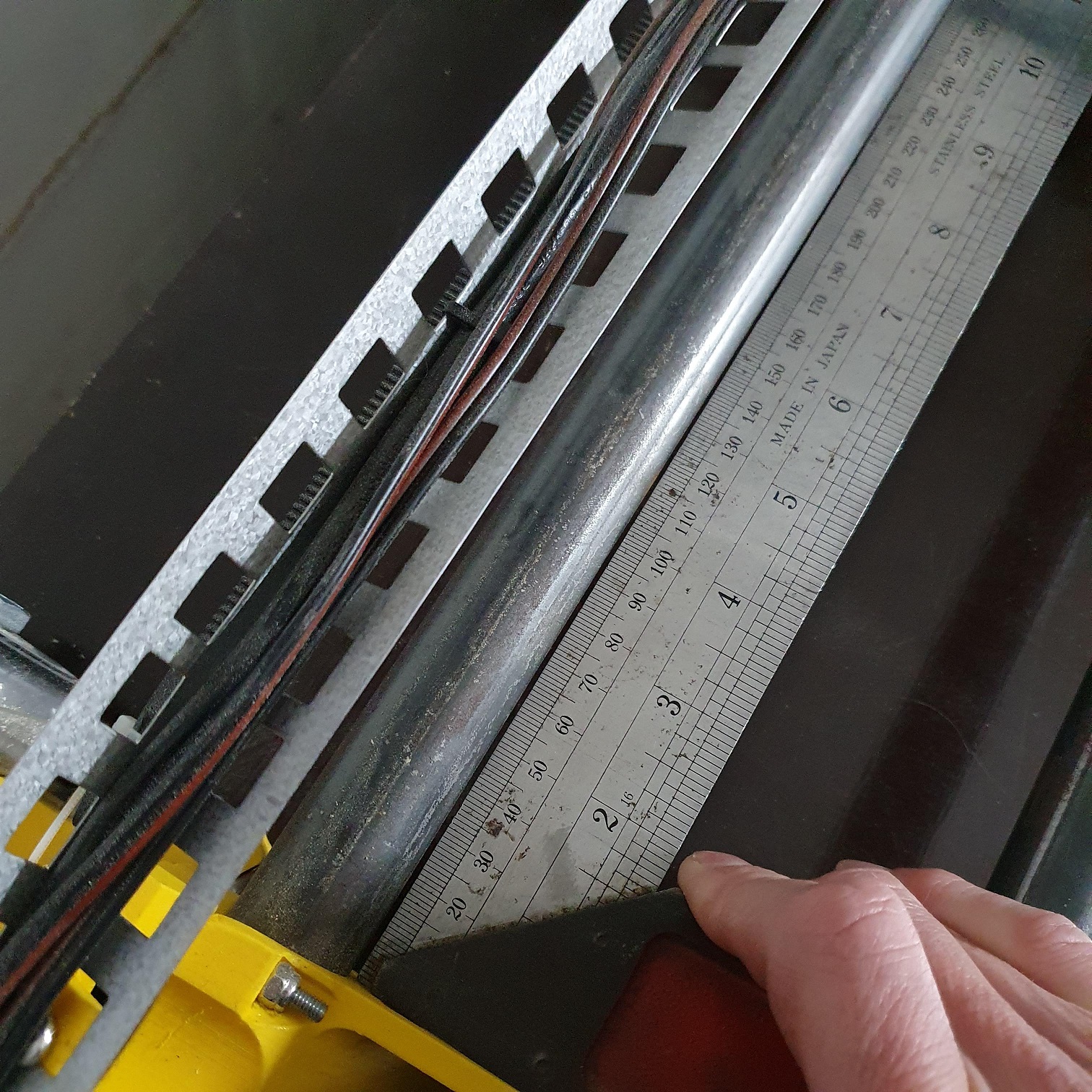
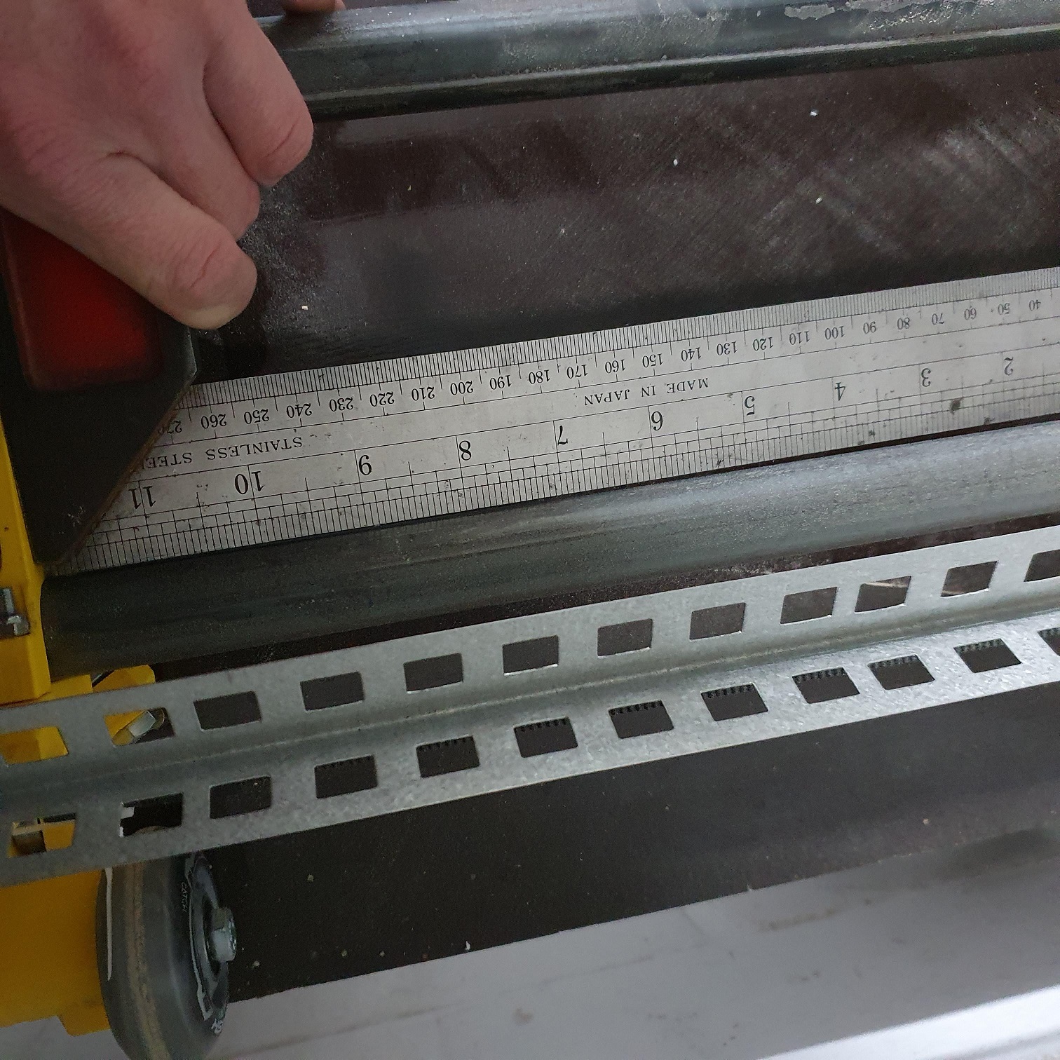
Ok, I’ve checked it and the seem to be 5 mm out of line.
So will adapt this whilst I am going to try and straighten my tubes once more. But I think it will be a bit waste of time, as I tried it few times now and always seem to end in exactly the same situation as I started:)
Yes, I figured, I always start by bumping my parking spot, it helps to align, but somewhere during travel it seems to move.
Going to think about how I can solve this. Was looking at the alu XY main too, as this would always be square, but the quotes I received were pretty expensive
 In a week or three we will see how much I think I’ve learned from it!