Lowrider 2 journey

So, I believe that I´ve passed the point of no return, and my Lowrider 2 journey is really starting.

After reading a lot on the subject, I thought to have a good idea what I´m into. However, after receiving nearly 60% of all parts, it seems that there will still be some questions to be answered.

What better to do this by making a build log?

Some background: I´ve got 0 experience with CNC, mostly this is outsourced for my little side hustle, by sending a sketch to a CNC company.

I hope to use the LR2 for some rapid prototyping. Materials I´ll want to cut are: Acrylic, Multiplex (Plywood?), Veneer and I am interested in EVA foam too.

Because of renovations, my workspace will be limited. In time I might upgrade to a full sheet size.
The workspace will be used for the LR2, and when not in use, it will function as a workbench.

It will be made out of 2 sheets 18mm Multiplex. Combined with 2 wooden beams to get a table height of ± 90cm.

The idea is to make some kind of a torsion box below the table deck to make it more rigid.

I choose to make it with Multiplex as I believe this will be to only material that will be level and straight. Here is a quick and dirty draft to get my idea.

01

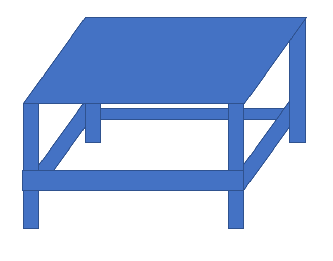
I made a draft on paper, calculated all parts, and imported my results in an optimizer tool. To maximize the design based on Multiplex sheet sizes.
The exact dimension will be 213,8 x 103,6 cm. The (single sided) torsion box wall will be 14 (top) and 10 cm (bottom) height.

Although, I am considering it to lower it to 9 cm at the bottom, so I could add an additional horizontal beam in the middle to increase sturdiness.
So, got to think about the final design once more, and get the wood so I can start building soon.

I initially wanted to buy parts in the V1 store. But calculating import tax, it became clear to source it in the EU instead. (sorry Ryan, if I lived in the US I would have ordered instantly as they are fair prices)

For others in the EU, also sourcing parts, some leads:

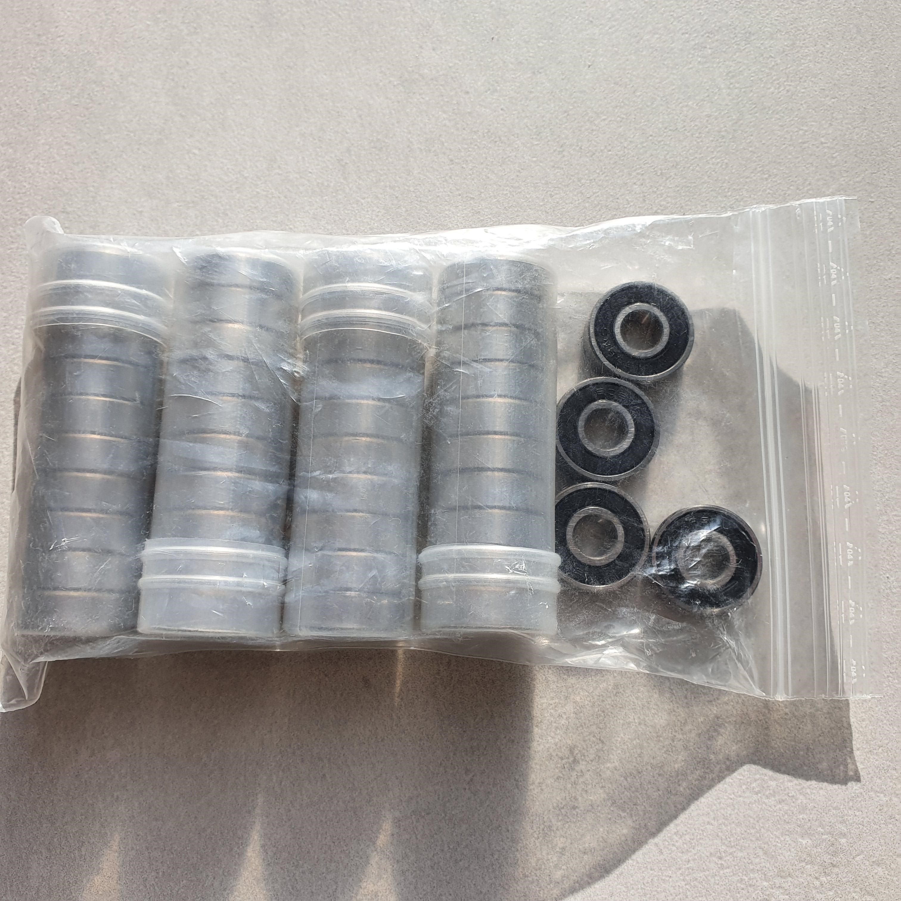
  • 608 bearings: Motedis, a German shop (warning slooooowwww handling of orders)
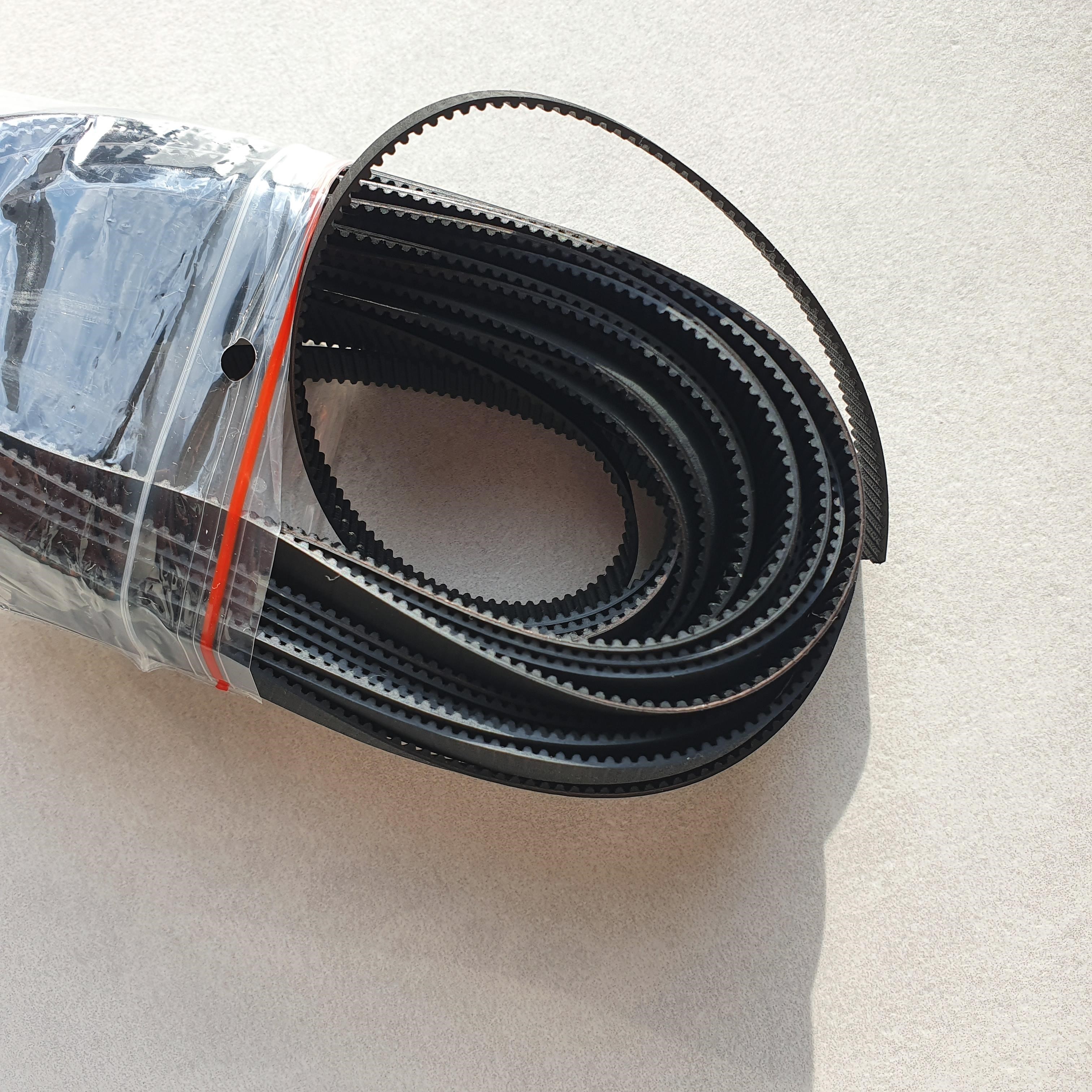
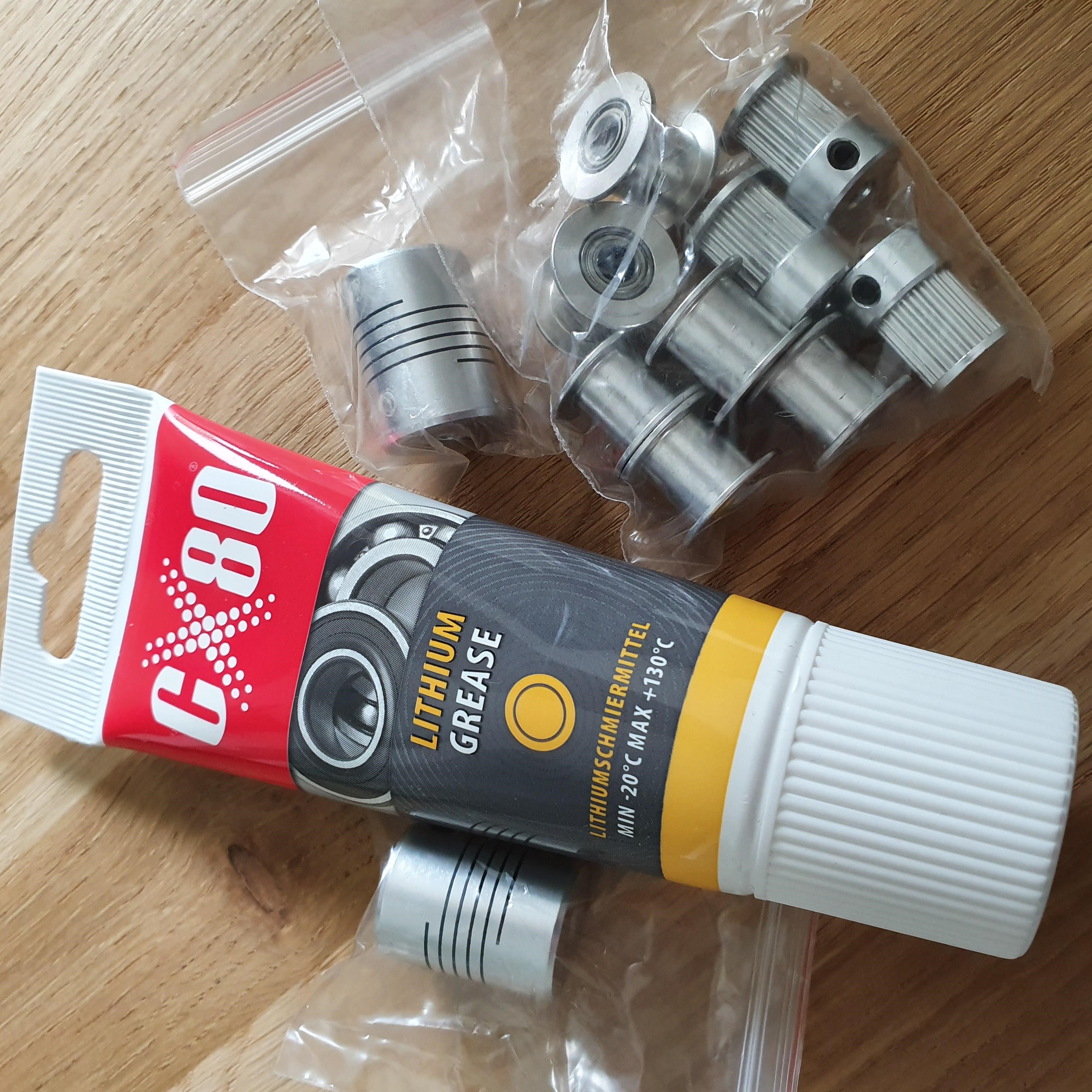
  • GT2: Hobby Store Poland has 10mm, fiber belts.
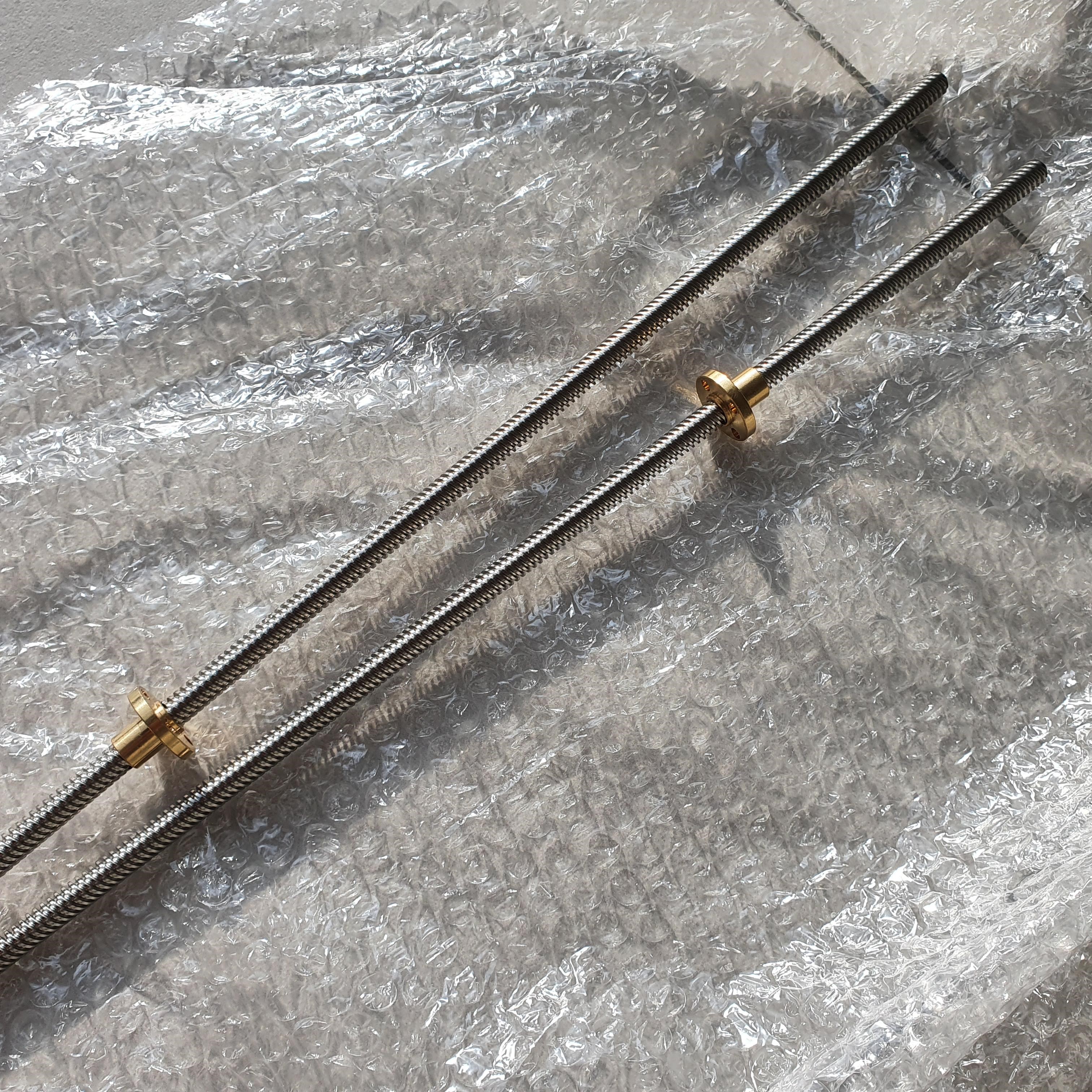
    The downside is that they only stock 20T instead of 16T. So will see if I need to change it.
  • Couplers, grease and leadscrew/nut also came from them. I probably went overkill taking 40cm instead of 30cm Leadscrews :blush:
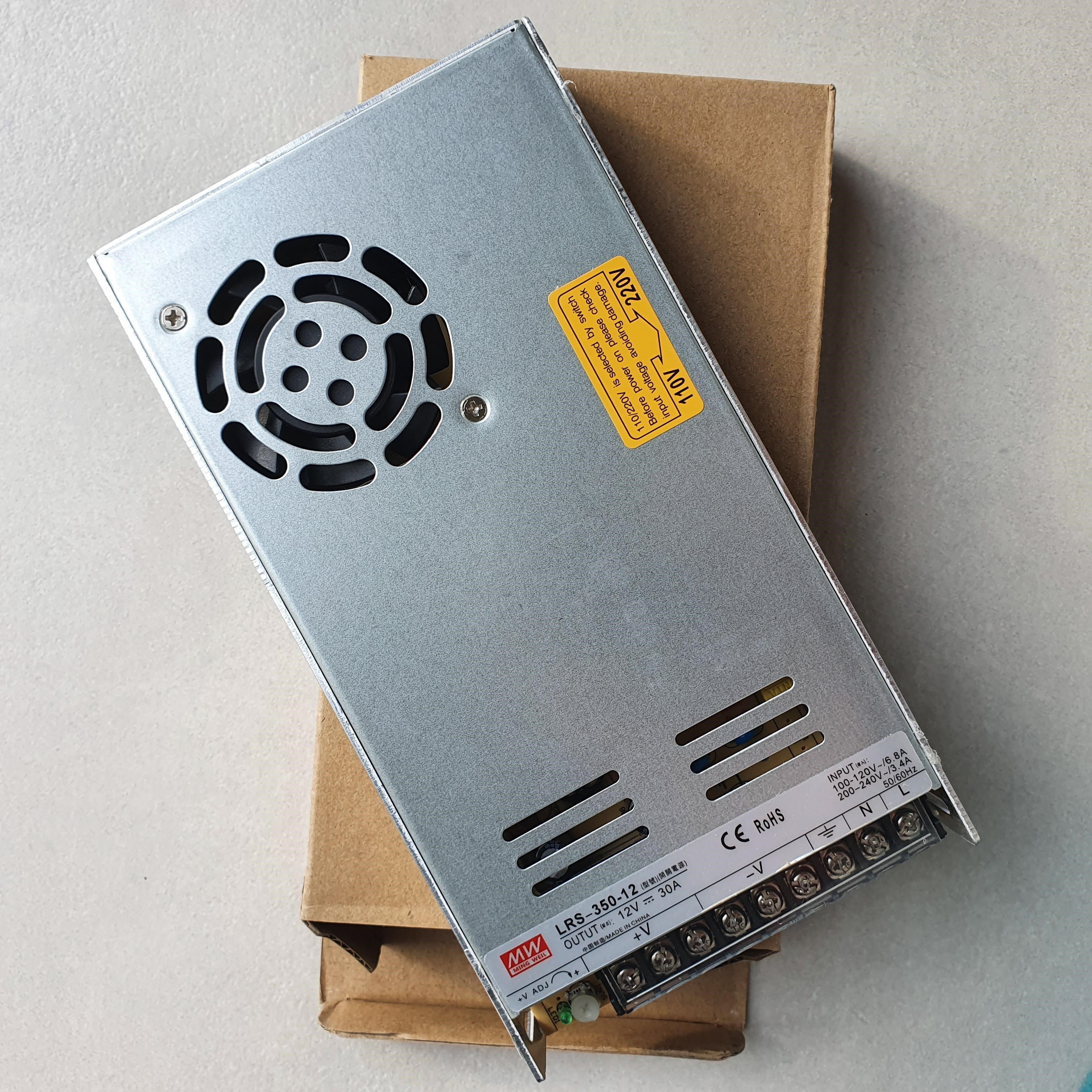
  • Power supply: I got a Meanwell copy: 12V 30A from Poland as well. Should be enough Ooomphh!
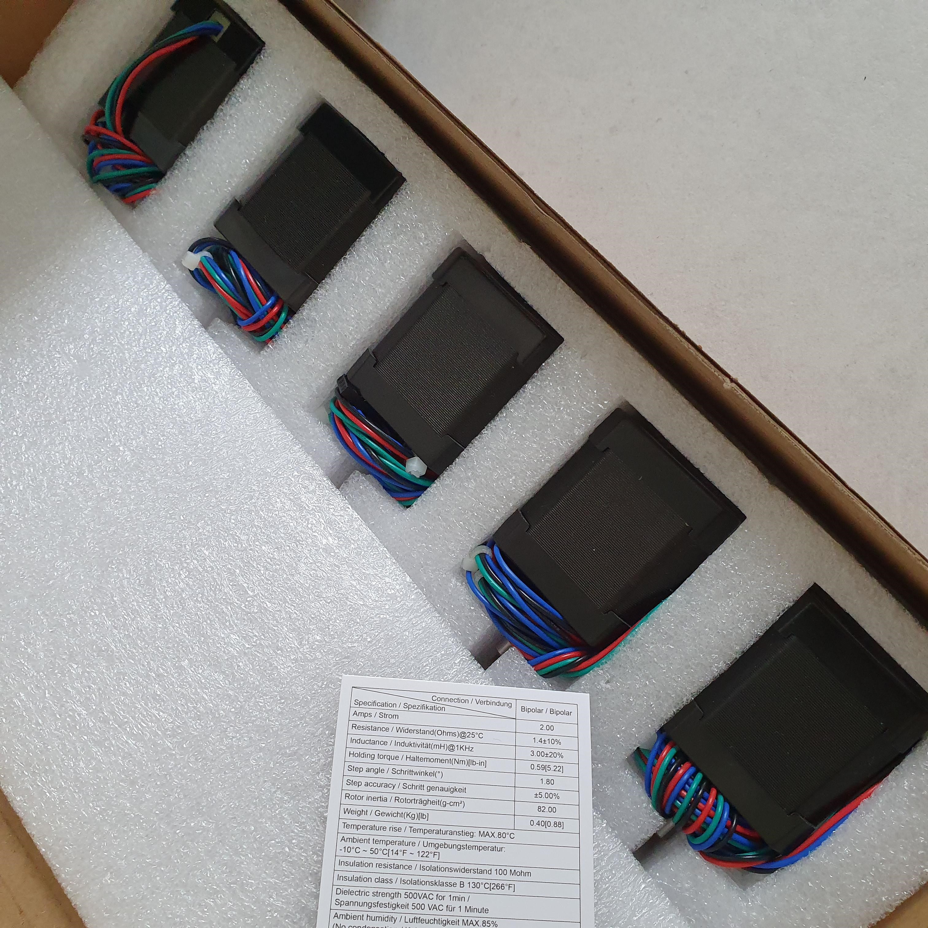
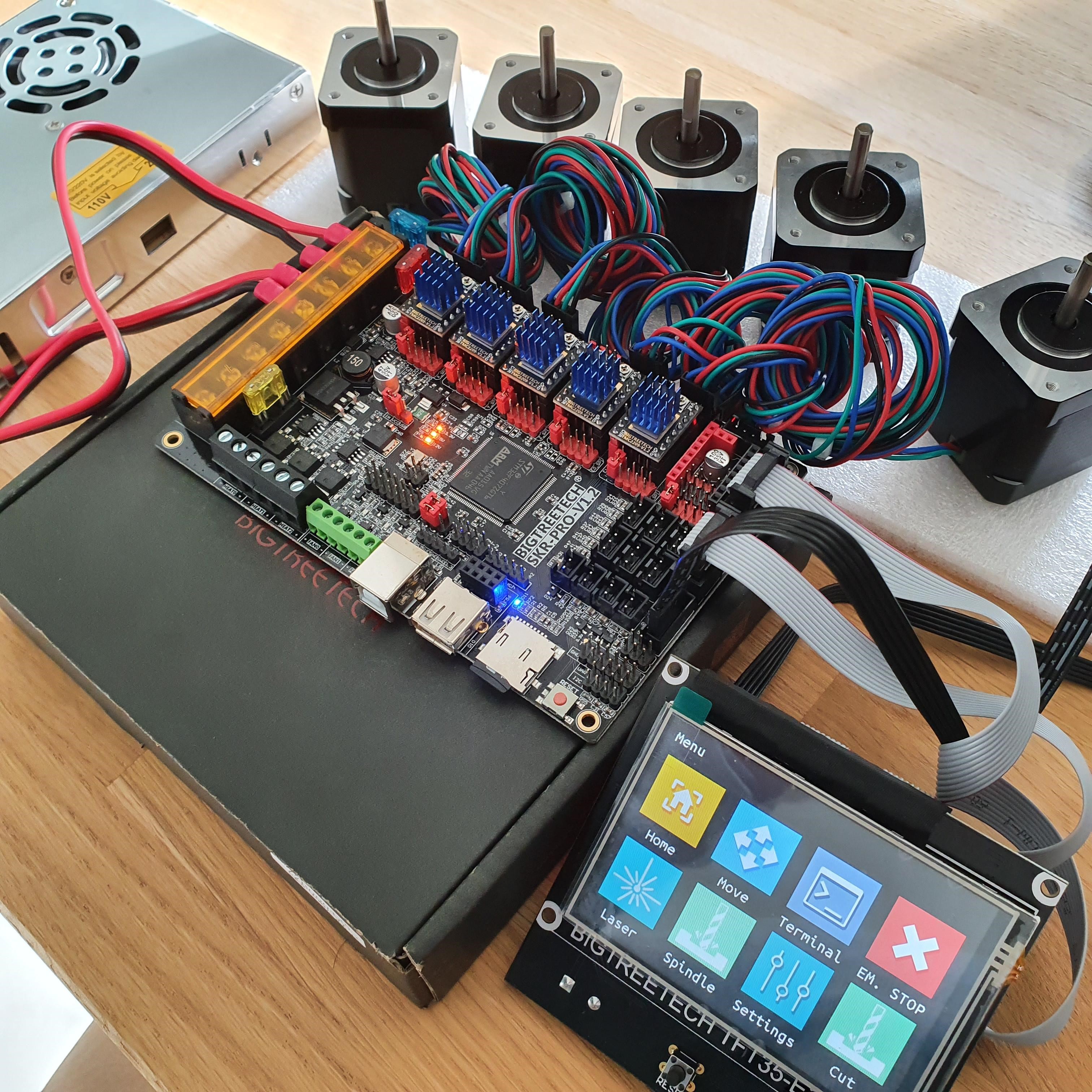
  • Stepper motors: I ordered the V1 recommended ones on Amazon Germany
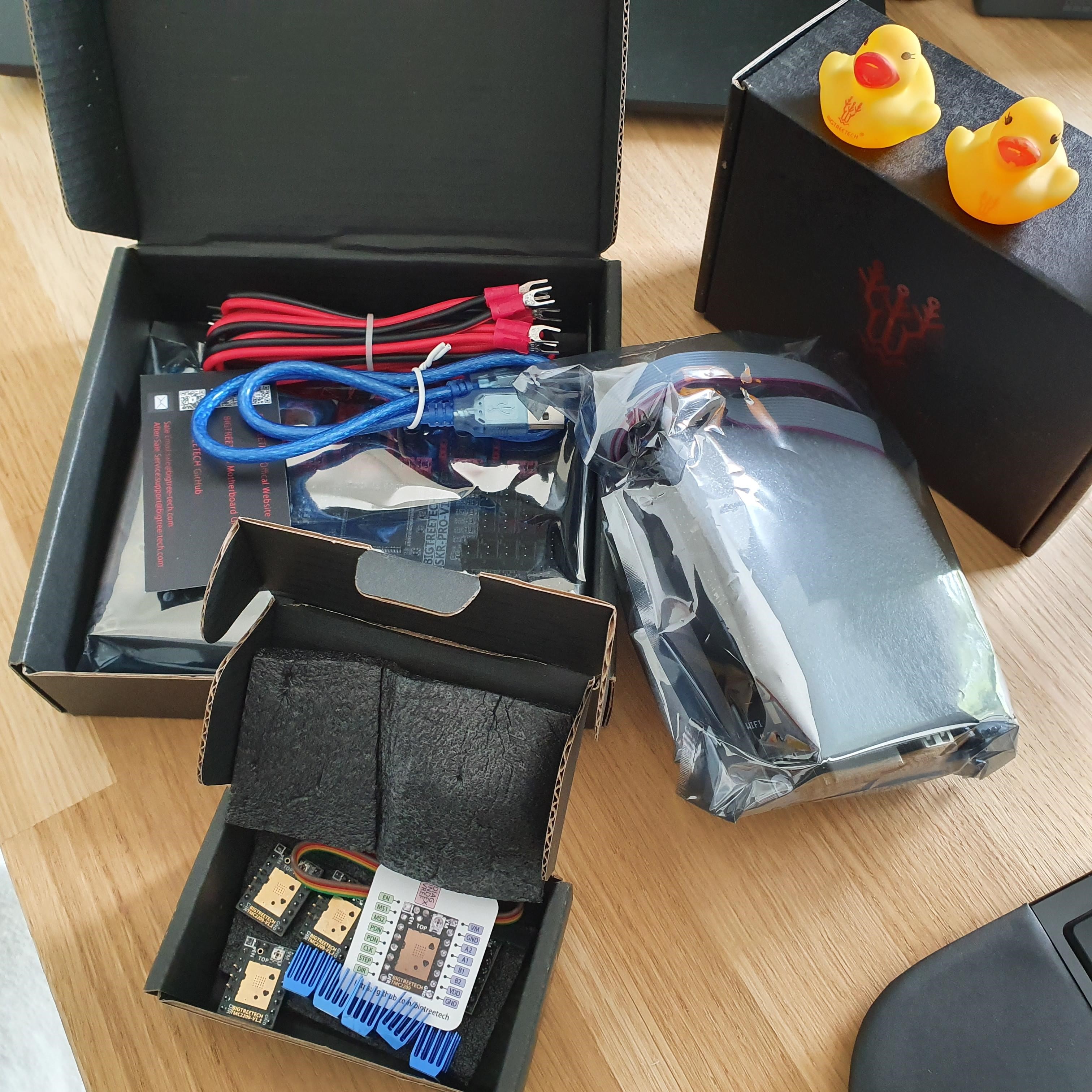
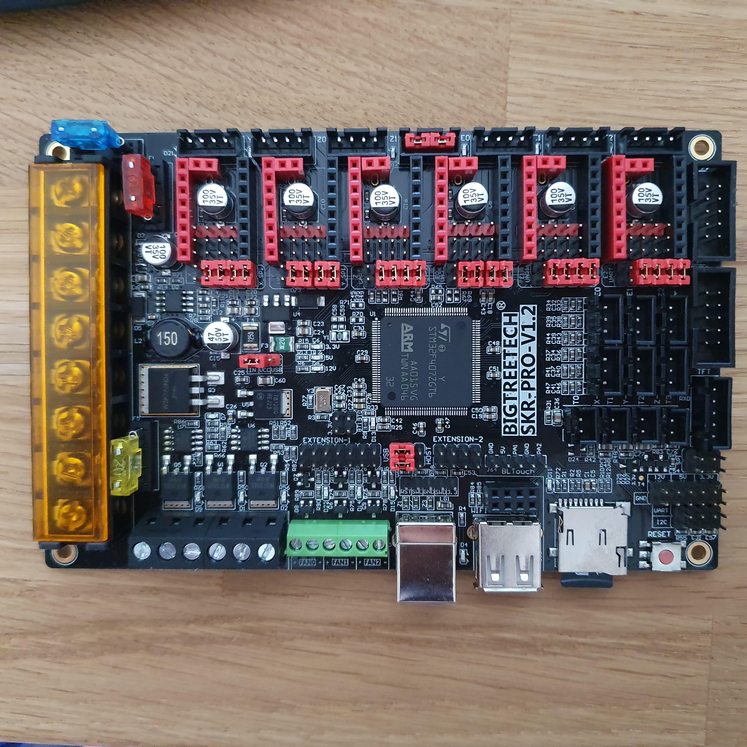
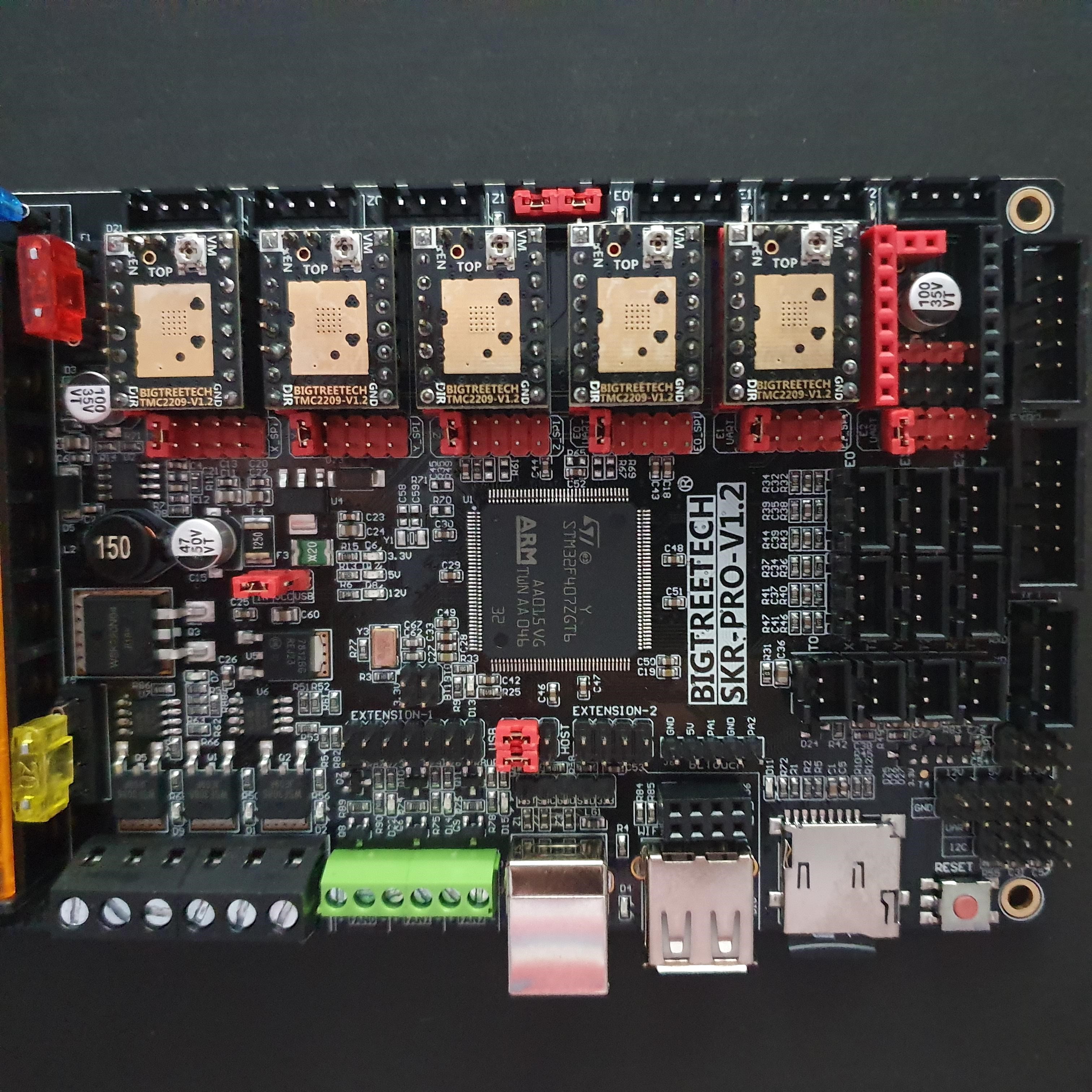
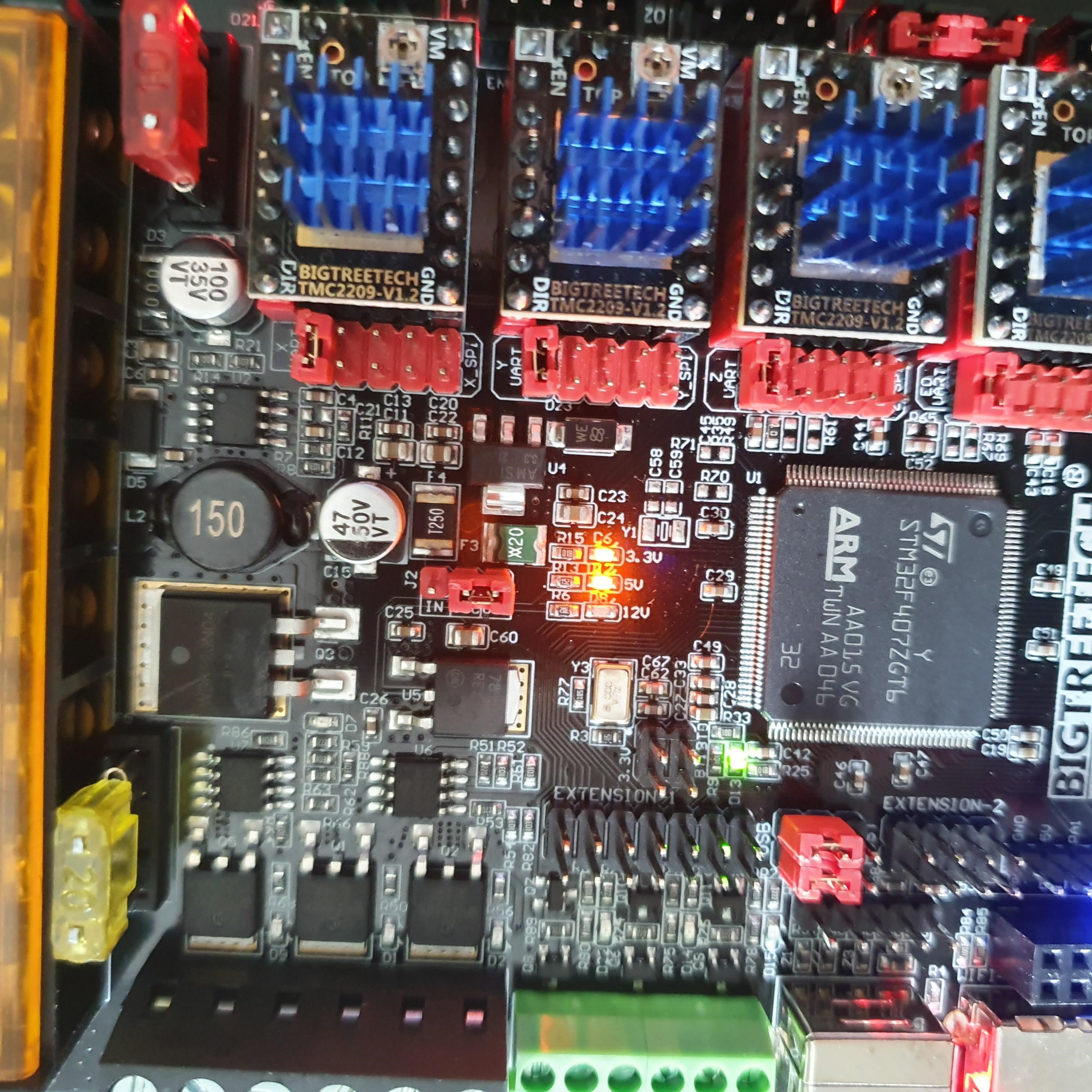
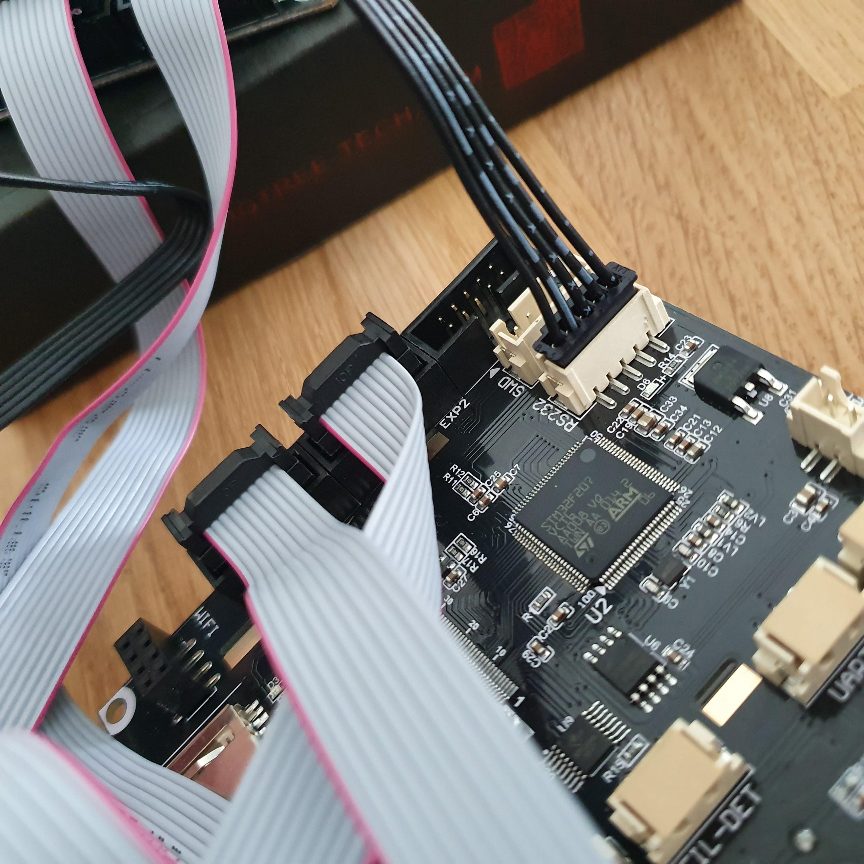
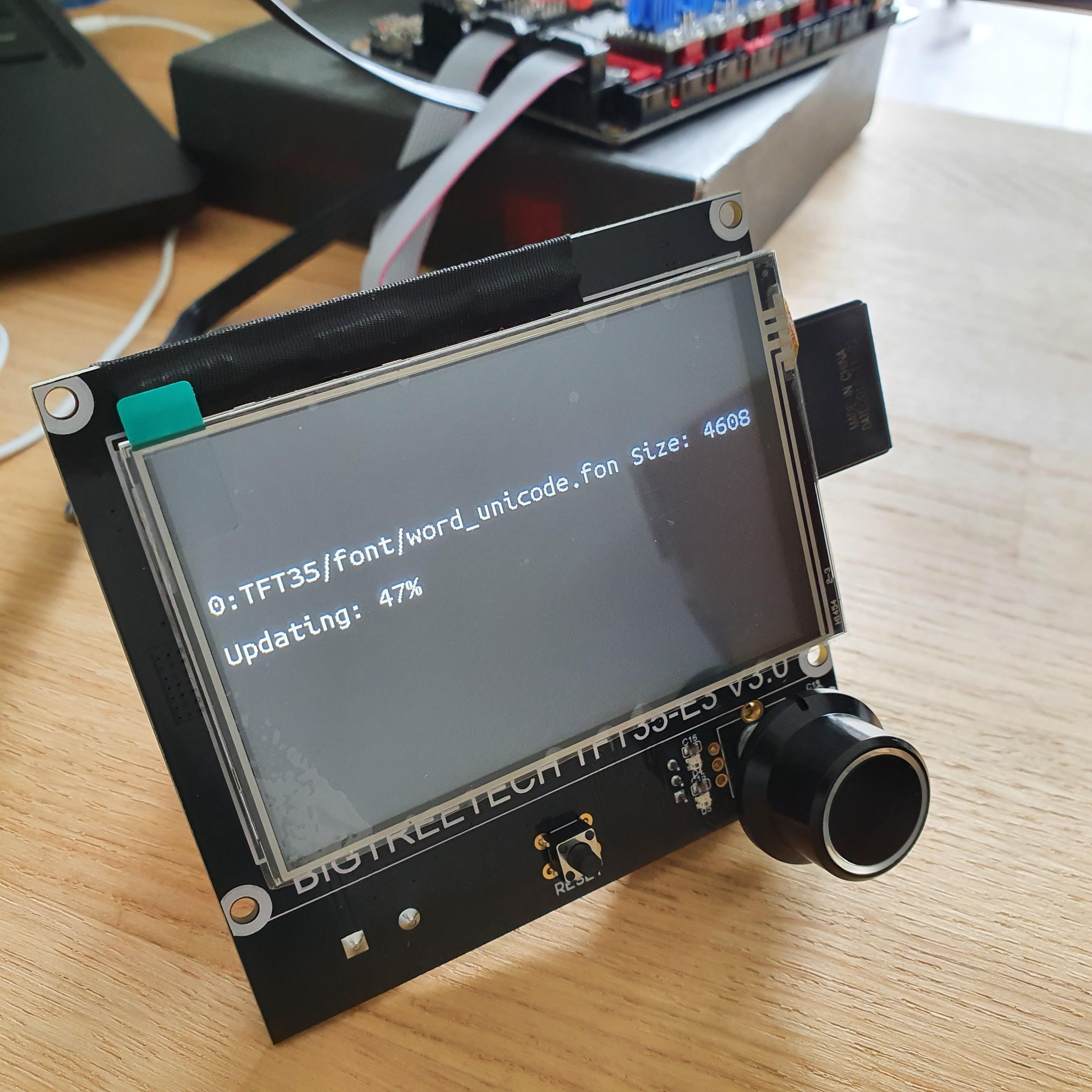
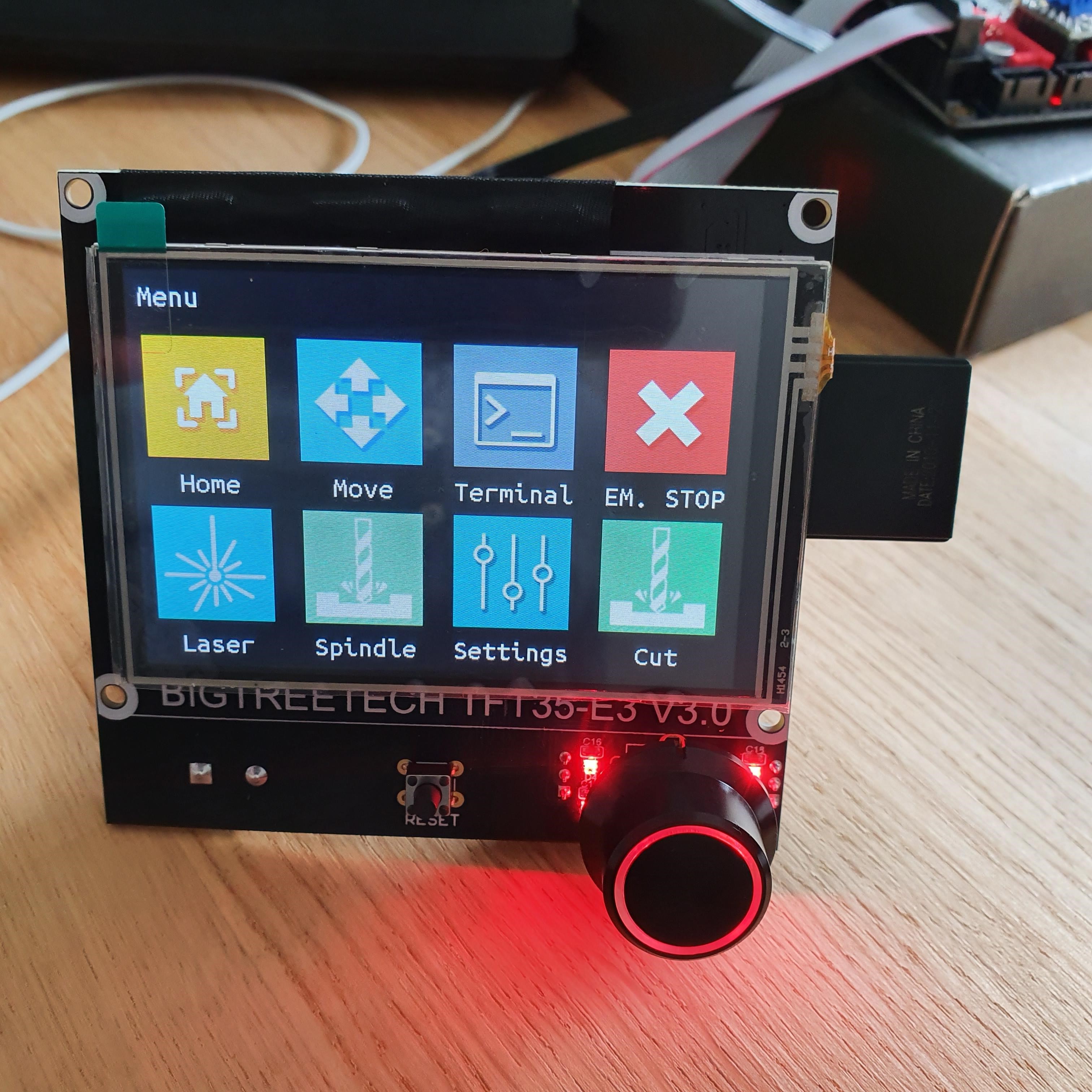
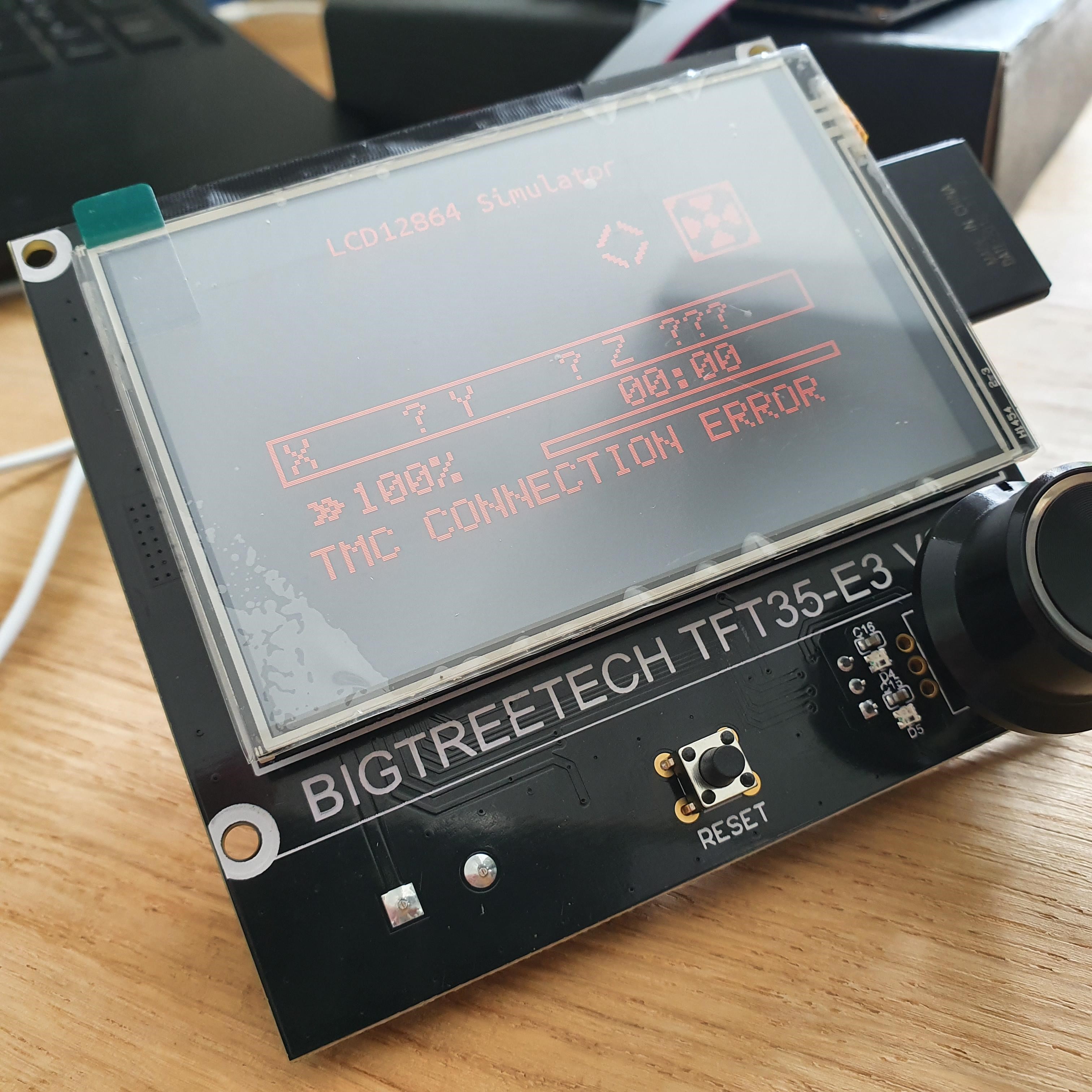
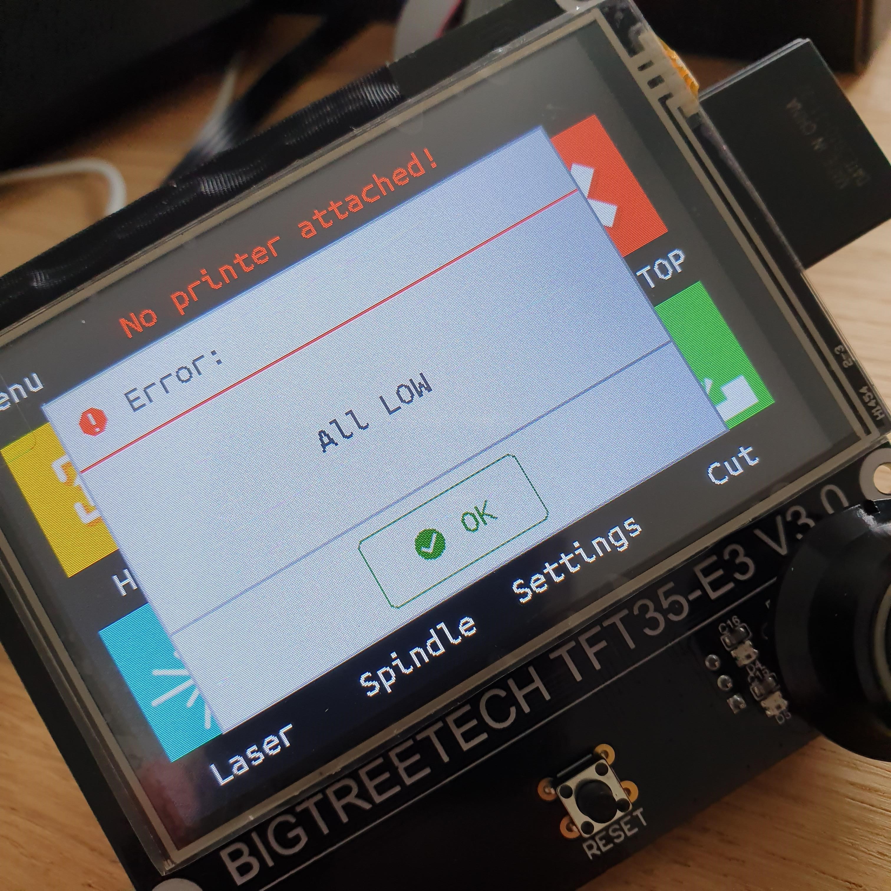
  • SKR Pro 1.2, 5x 2209 drivers, TFT V3 E3: Amazon Germany, same price as V1 shop.
  • 60mm wheel & spacers: Skate Dump Netherlands, 0,5€ per wheel. However I am still waiting for them to be delivered.
  • Hardware: DHZ proshop Belgium – you can buy the exact amount you need.
    Warning: take a good look at your cart, it was that cheap I accidently ordered 6 boxes of lock nuts. So I got 1200 of them instead of 6 :smiley:
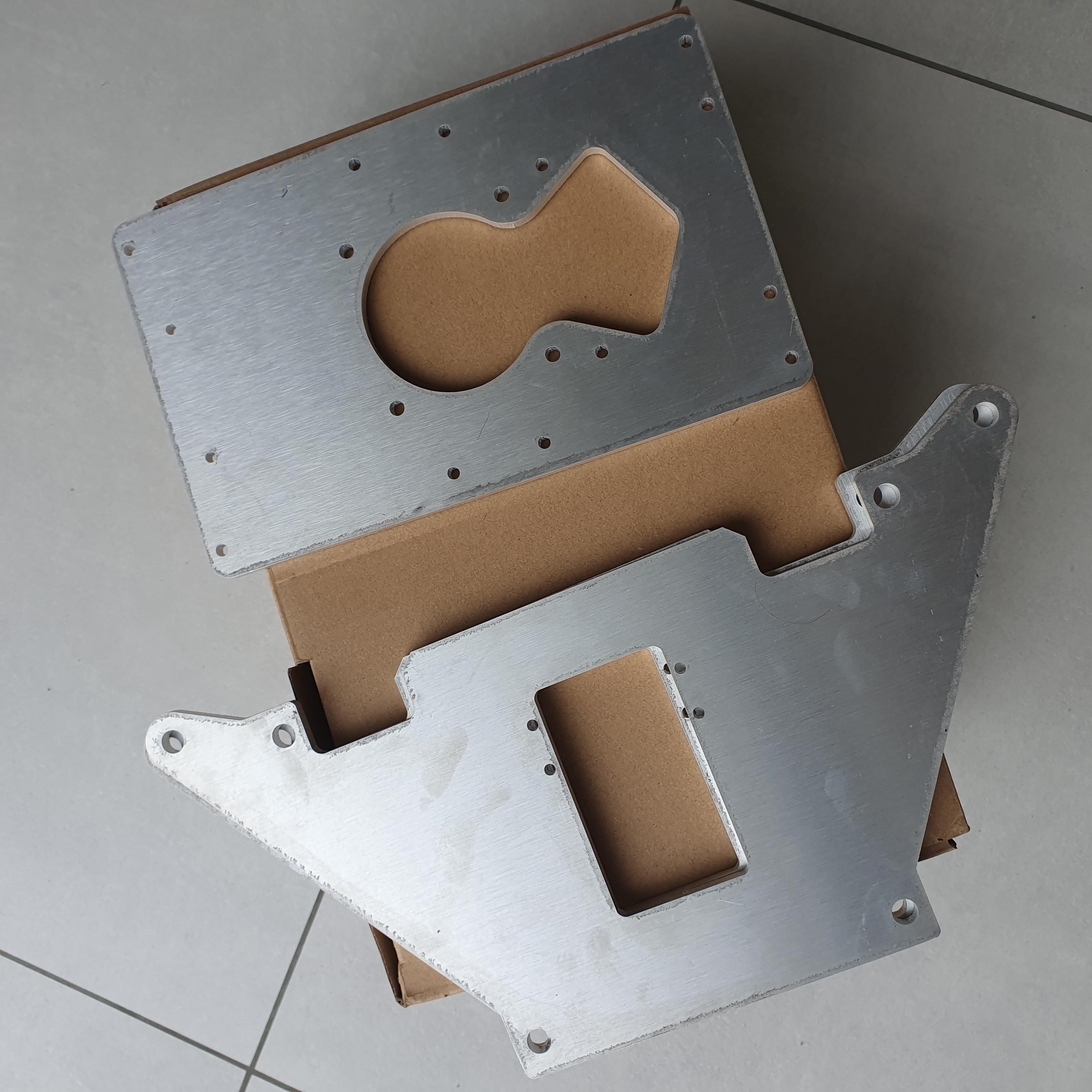
  • Flat parts: I ordered the Alu ones from Bozpet (check the “For Sales”-channel). I expect them any day now.

I will still need to buy the pipes, and a spindle. But this will be done when nearing completion of the table…


Now up to my questions, hope anyone could help me.

During the weekend I wanted to start on the SKR Pro configuration. But I doubt if I understand the FAQ correctly.

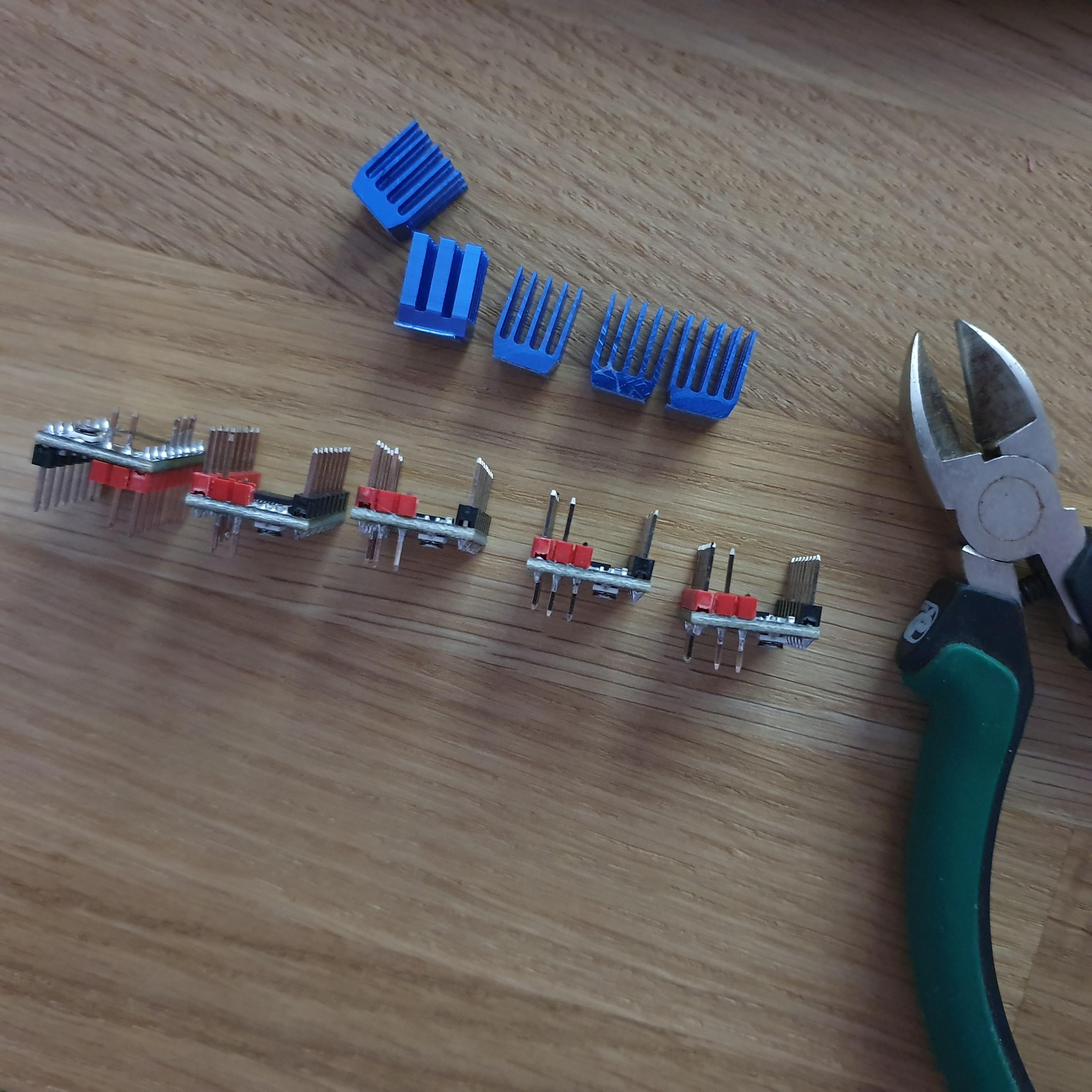
I want to use auto square functionality. AKA Dual End Stops. The FAQ mentions to remove the Sensorless pin.

Do I need to do this for Dual End Stops? Why not just keep it?
And, I believe it would be best to remove it instead of bending? To avoid shorts and static noise?

I also wonder about the default V1 software configuration. The FAQ speaks about EXTRUDERS=0 or EXTRUDERS=1.
As I understand it, it depends on where I add a stepper driver, and where I wire the stepper motor.
But what is the default configuration of the default V1 firmware? Is it =0 or =1?

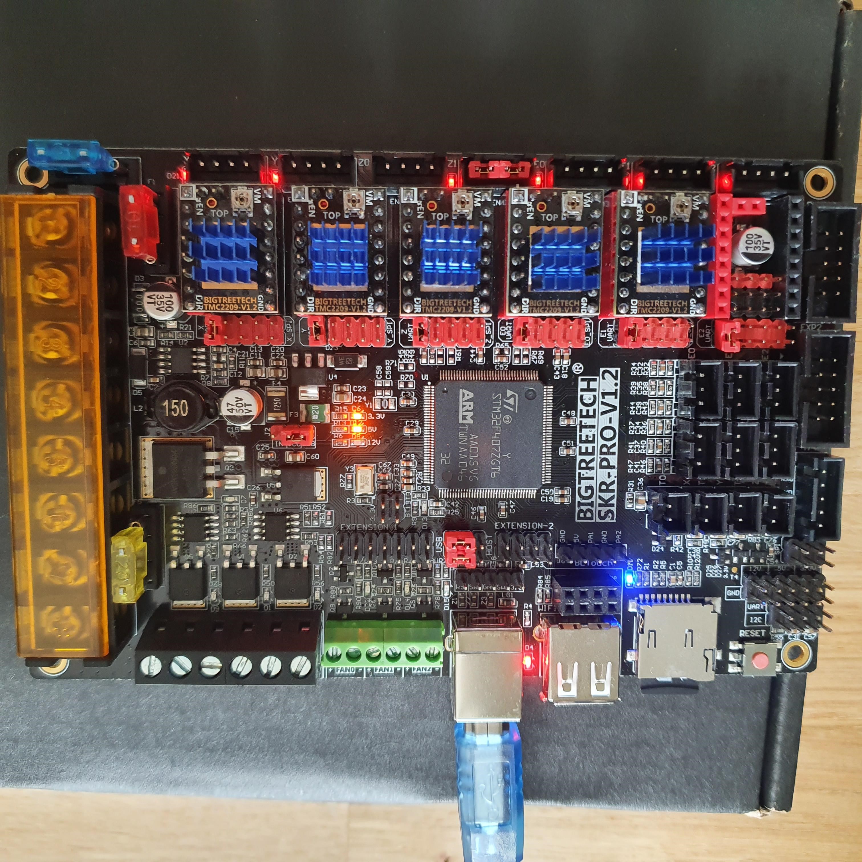
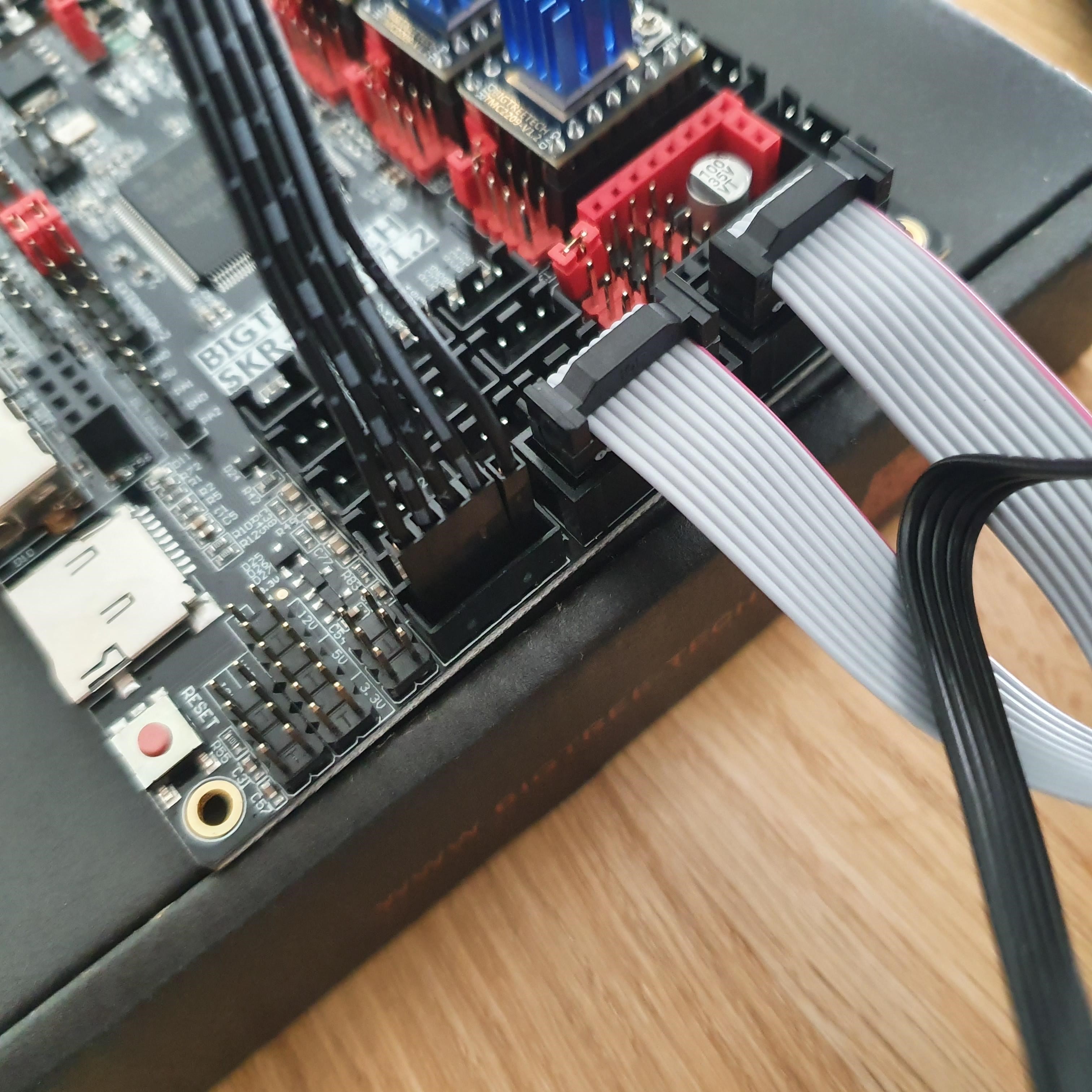
The SKR did not come with a manual. How do I wire the power supply? The FAQ shows 4 wires, is that the way to go? My common sense thinks that 2 wires should be enough :smiley:

Did anyone re-solder the stepper motor connectors? I do not like them to be removed as the FAQ suggests, I´d rather solder the correct connector to the stepper motor instead.
Can anyone confirm that it should be JST-XH connectors?

Final question; how many switches are needed for Dual End Stops?
My common sense says; 2x on each X, 2x on Y, and at least 1 on Z (touchplate not including). So that would be 7?

However the FAQ shows only 5 connectors to be plugged in? :smiley:

2 Likes

The SKR Pro has two power inputs, one for the board and a separate one just for the Motors. Both inputs need to be powered. There is a basic manual available from the BTT Github page. BIGTREETECH-SKR-PRO-V1.1/SKR-PRO-V1.2 at master · bigtreetech/BIGTREETECH-SKR-PRO-V1.1 · GitHub

JST-XH are the connectors on the board.

Basically you have an end-stop per motor so 2 on the Y axis, 2 on the Z axis and 1 on the X axis.

2 Likes

Hi Fraser,
thanks for the confirmation!

Regarding the End Stops, ok, I´ll order 5 switches then.
But I am still confused about it :slight_smile:

On the X axis (the length) you have the two side-parts on hockey wheels that move. I´d imagine you would have a start + end switch for both of them? Because they move independent. So they could be out of sync, no?

We may be getting confused between axis names, I call the Length that the wheels travel along as the Y axis.

So to try and make it clear, The axis that runs on the wheels needs 2 switches, the axis that carries the router plate needs one switch and the axis that lifts the machine requires 2 switches.

Make sure you’ve read the skr pro doc here:

https://docs.v1engineering.com/electronics/skrpro/

And the dual LR info here:

https://docs.v1engineering.com/electronics/dual-lr/

The current choice is EXTRUDERS=0.

You can bend or cut the sensorless pin, or desolder it.

You´re right. I am sure that there will be a “golden standard” in CNC and it´s defintions, but I don´t know them yet:)

I looked at it this way. So the longest side is the X, shortest, the Y.

Do I understand you correctly, that using the linked image as definition, you would add 2 switches on one side of the X axis, where both steppers are mounted? And that you, for squaring will only run to that side?

I had the idea you would block all corners, making sure that the axis can not outrun the workspace :slight_smile: But now it seems to me that it is only used to square?

Thanks, I did read it, however not being native English some minor details seems to escape.
With the SKR manual, linked by Fraser, it makes sense now.

With the risk jumping from one thing to the other one;
I did check out your Headless Pi solution. What would be the benefit (other then the webcam) against using the Wifi of the SKR?

Yes.

1 Like

We don’t have the firmware set up for the wifi yet. I am also not sure how it will work with the sdcard.

Great, thanks for the confirmation!

I wonder if there´s no risk, that the L2 runs out of workspace? If there´s no end switch on the other end?

Or will this be one of the many items on the checklist before using the CNC machine?

Ok, something I will need to try then. I´ll order an ESP-01S together with the limiting switches and will give it a go. If I can still find my flashtool from few years back :smiley:

So, last night I made some time to do the initial setup of the board based on the FAQ instructions.
First, I removed the jumpers below the drivers mount, cut away the sensor pin (as I did not find my soldering iron quickly), mounted the cooling elements and finally mounted it all to the board.


Now it is time to upload the firmware.

Because the FAQ mentions to remove TFT cabling, I´ll do the update without connecting the TFT at all. Just to be sure.

However, to upload the firmware to the TFT I do have a question. The FAQ doesn´t explicitly mentions if I should remove certain cables, like when updating the motherboard.

So would it be ok to connect all wires during this upgrade?

Endstops are ignored unless you are homing. They won’t stop the machine. That’s ok. It will skip steps, but not break any motors or anything. The one part that it in danger on the low rider is the coupler, which can stretch if you go too far down.

Just plug in the 5pin black cable to update it. Then the gray ones. That seems to be safest.

1 Like

Ok, that makes sense. Seems I´ve got to let go some of my thoughts and start to learn thinking like a CNC machine :slight_smile:

Yes sir!

So I did the updates.
First I modified the jumper, to use USB power. Because I had to look for a power cable otherwise.


Next I did the update, and like noted in the FAQ; the green LED blinked a few times, and it was as easy as this :slight_smile:

So, I hooked up the TFT, double checked the cabling (cable indicators are different on mine then in FAQ)

Started the Update procedure.
Note for new users, there´s no big SD adapter in the box. So make sure to get one first.

And voila! It looks like a CNC interface :wink:

However, once I swapped between the interfaces, I got an error.

My guess, or hope, is that this is caused because there are no steppers connected.
Will see if I can find some time tonight or tomorrow, to hook up a power cable and some motors.

You shouldn’t be seeing the TMC Connection error even though you haven’t connected the stepper motors.

How are you powering the SKR board?

1 Like

Pretty sure that the TMC drivers don’t like not having Vin. You’ll need power to “motor power” as well as the logic power. (USB will be OK for logic power if you’ll always have it.)

3 Likes

Well, I was thinking the same, but;

It seems that they need power, indeed!

Connected steppers and the power supply, and there was no more such message…
Until I pressed the reset button. Then the message popped up again.
It went away after a full power cycle, so I am going to ignore it for now :blush:

On the menu there´s the “Laser” and “Spindle” button:

I noticed, when enabled, that a led on the screw terminals went on. Am I correct that one would connect a relay to this screw terminal. So one could enable/disable power to the spindle?

I will be using a Makita spindle. Not sure if it will be a good idea to use this functionality over the normal power button on the spindle? I couldn´t find any topic about this on the forum :frowning:

I also wondered about the emergency stop. I believe that this will “pause” the job once the logic receives this message. Would it be best to add a switch, to the full power bracket, so that everything really powers off immediately. In case of emergency?

I’m a big believer in “Emergency Stop” being equivalent to “remove all power from everything.” Some folks do this as simply as having everything plugged into a single outlet strip with one off switch. I’ve got an e-stop switch in the hot line AC power coming into my control box, so it catches the DC power supply for the steppers as well as the AC power that feeds the spindle.

2 Likes

That makes sense!
I´ll get a “real” emergency stop, so I can kill everything in one button. Better safe than sorry :slight_smile:

I think an emergency button also needs to open a void and send the machine into it, along with a small charge to disable every part once inside the void.

Short of that, cutting power is generally pretty reliable.

1 Like

Profit motives behind SawStop and other parallels are now occurring to me - ensure the bit/blade as well as the brakes require replacement (at significant cost) each time the e-stop is hit. I’m imagining a 16-ton weight (a-la Monty Python) dropping down to ensure all motion is halted.

Wow, never heard of this brand, but looking up their website it is impressive. Although, I still don´t like to see my fingers close to it :stuck_out_tongue:

Jeffeb3 has a point, that it should immediatly kill the rotational force of the spindle. But I don´t think this will be feasible in a DIY solution. Could be wrong though.
So I´ll get my hands on a simple emergency switch to kill power of the SKR & Spindle at the same time and let´s hope I´ll never use it!

Guess what?
The delivery guy just showed up, with a package. From Portugal.
Kudos @bozpet for helping me to get my hands on some clean laser cut alu flat parts.

In my hurry I made an error though, to take the default Dewalt version, instead of the Makita I will be needing. But we´ll figure out how to make it work:)

Now I´ll need to start reading the building FAQ :slight_smile:

3 Likes